18
Curtis 1298 Manual, OS 11
Analog inputs
Two control lines can be used as analog inputs. Both inputs are protected
against shorts to B+ or B-.
Typically Analog 2 is used as the input for the motor temperature sensor.
This input provides a constant current appropriate for a thermistor sensor. Some
standard predefined motor temperature sensors are supported in software (see
Sensor Type parameter, page 49). Note: The industry standard KTY tempera
-
ture sensors are silicon temperature sensors with a polarity band; the polarity
band of a KTY sensor must be the end connected to I/O Ground (pin 7).
These lines can also be used as digital inputs, and are included in that
group as well.
2 — INSTALLATION & WIRING: I/O Signal Specifications
Analog output
A single line is available as a low power analog output and is intended to drive
instrumentation such as a battery discharge indicator. This output is generated
from a filtered PWM signal and has about 1% ripple. The 2% settling time
is <25ms for a 0–5V step and <30 ms for a 0–10V step. This output line is
protected against shorts to B+ or B-.
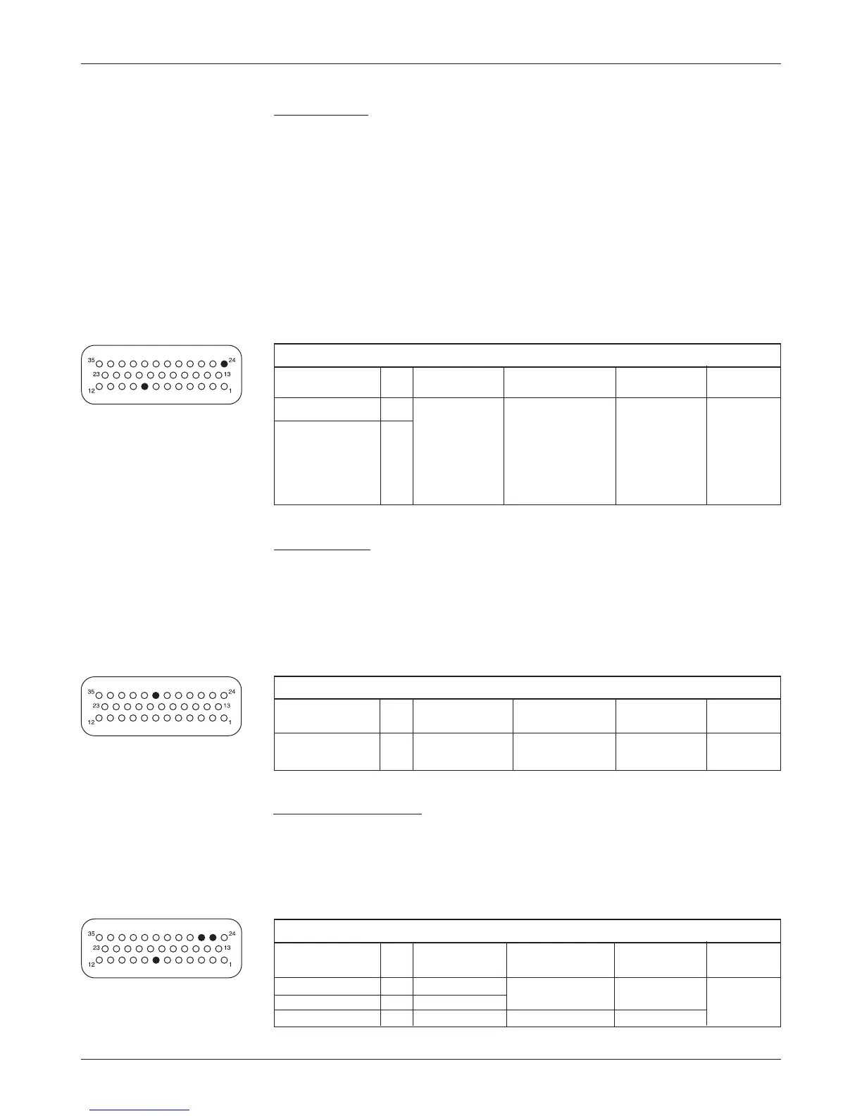
POWER SUPPLY OUTPUT SPECIFICATIONS
OUTPUT
OUTPUT PROTECTED ESD
SIGNAL NAME PIN VOLTAGE
CURRENT VOLTAGE TOLERANCE
+12V Out 25 11.5 to 14.5 V 200 mA max - 1 V to ± 8 kV (air
+5V Out 26 5 V ±5% (combined total) (MaxV + 10 V) discharge)
I/O Ground 7 n/a 500 mA max not protected
ANALOG INPUT SPECIFICATIONS
OPERATING
INPUT PROTECTED ESD
SIGNAL NAME PIN VOLTAGE
IMPEDANCE VOLTAGE TOLERANCE
Analog 1 24 0 to 10 V in 24-36V models: - 10 V to ± 8 kV (air
Analog 2 8 1024 steps
about 7.1 kΩ (MaxV + 10 V) discharge)
36-48V models:
about 11.0 kΩ
48-80V models:
about 26.0 kΩ
ANALOG OUTPUT SPECIFICATIONS
OUTPUT
OUTPUT PROTECTED ESD
SIGNAL NAME PIN VOLTAGE
IMPEDANCE VOLTAGE TOLERANCE
Analog Out 30 0 to 10 V Source: 100 Ω - 1 V to ± 8 kV (air
Sink: 66 k
Ω (MaxV + 10 V) discharge)
Power supply outputs
Two lines provide auxiliary output power for low power circuits such as elec-
tronic throttles, LED indicators, displays, position encoder, and remote I/O
boards. I/O Ground (at pin 7) is the return line for these low power devices.
Both power supply outputs are protected against shorts to B+ or B-.
☞