Curtis 1298 Manual, OS 11
19
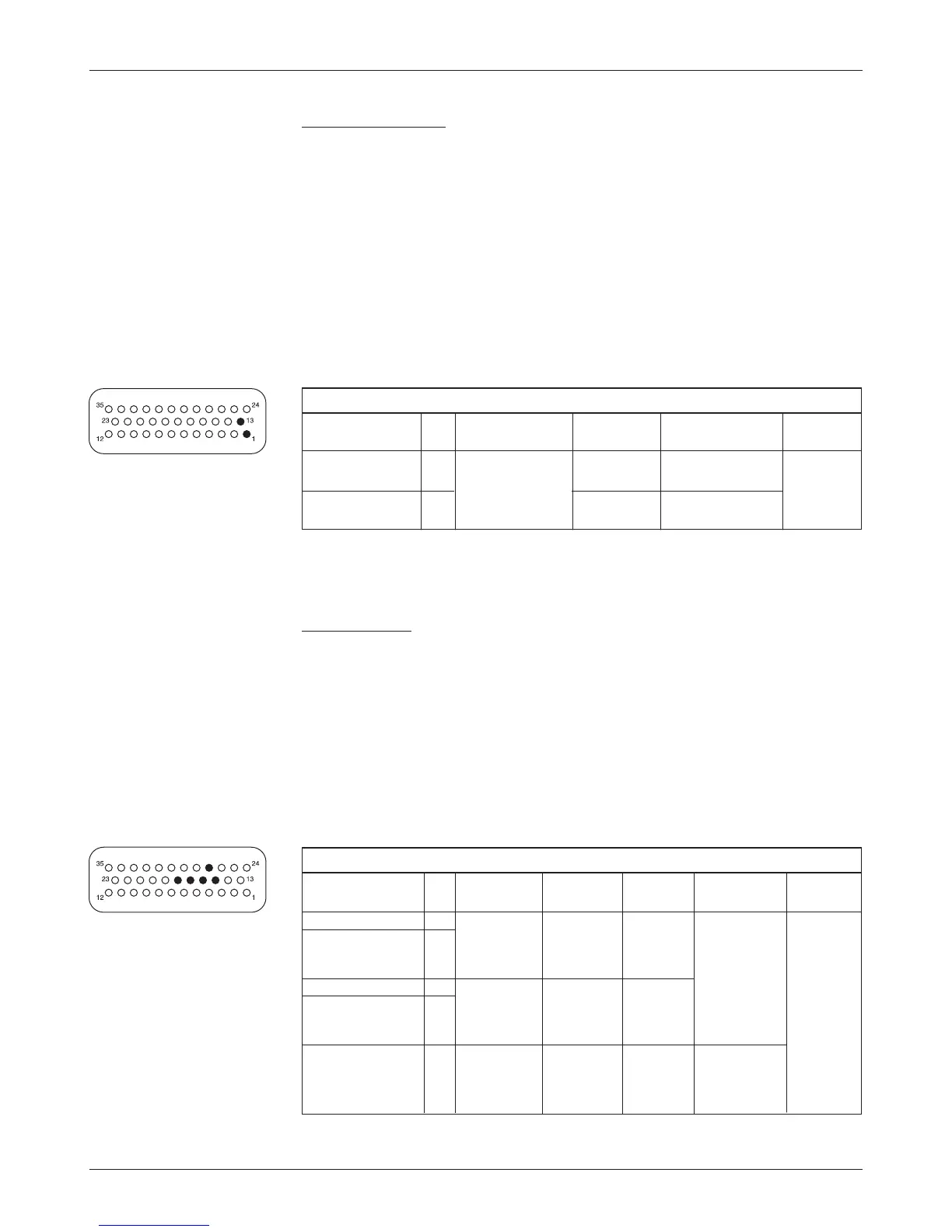
2 — INSTALLATION & WIRING: I/O Signal Specifications
KSI and coil return
KSI input provides power for all low power control circuits, power capacitor
precharge (before main contactor turn on), power supply outputs, and high
power output drivers. Battery voltage is sensed on the input for the VCL bat
-
tery discharge function.
Coil Return should be wired to the positive battery side of the contactors
being driven so that switching noise associated with PWM operation of the
contactors is localized to the contactor wiring only.
It is important to maintain the division between KSI and coil return
in order to ensure reverse polarity protection (vehicle wiring correct, battery
terminals reversed).
Throttle inputs
The two pot inputs are independently programmable to allow use of a voltage
throttle or a 2-wire or 3-wire resistance throttle. Voltage throttles require only
the Pot Wiper input (with I/O Ground for the return line). Resistance throttles
require Pot Wiper and Pot Low (2-wire) or Pot High, Pot Wiper, and Pot Low
(3-wire). All throttle I/O is protected against shorts to B+ or B-.
Alternatively, these two inputs can be used for analog signals other than
the throttle pot inputs. Configuring the inputs for use with other signals requires
VCL programming; see Section 7.
THROTTLE INPUT SPECIFICATIONS
OPERATING
INPUT S/SINK PROTECTED ESD
SIGNAL NAME PIN VOLTAGE
IMPEDANCE CURRENT VOLTAGE TOLERANCE
Throttle Pot High 15 0 V (shorted n/a 7 mA - 50 V to ± 8 kV (air
Pot2 High 27 to Pot Low) nominal (MaxV + 10 V) discharge)
5 V (open (source)
circuit)
Throttle Pot Wiper 16 0 to 6.25 V 290 kΩ 0.76 mA
Pot2 Wiper 17 (voltage nominal
and 3-wire) (source,
2-wire)
Pot Low 18 0 to 10 V 20 Ω nom. Faults if -1 V to
above (MaxV + 10 V)
11 mA
(sink)
KSI AND COIL RETURN INPUT SPECIFICATIONS
OPERATING
INPUT PROTECTED ESD
SIGNAL NAME PIN VOLTAGE
CURRENT VOLTAGE TOLERANCE
KSI 1 Between under- 1.0 A max
*
± (MaxV + 10 V) ± 8 kV (air
and overvoltage discharge)
Coil Return 13
cutbacks
12 A max
**
(KSI - 0.3 V) to
(MaxV + 10 V)
* Additionally must carry the current supplied to the driver loads by the coil return (pin 13).
** The combined current supplied by all seven output drivers should not exceed 10 A.