1155
6699
RS232 SERIAL INTERFACE
Female DB9 connector
J1
1 DCD
2 TX During transmission, takes the values -VRS232 and + VRS232 depending on data
3 RX During reception, takes the values -VRS232 and +VRS232 depending on data
4 DSR
5 GND
6 DTR When +VRS232, device is power on
7 CTS
8 RTS When +VRS232, device is ready to receive data
9 n.c.
NOTES:
Given the presence of the RS232 standard, logic value “0” corresponds to the voltage value +VRS232 (voltage value
between +3Vdc and +15Vdc) and logic value “1” corresponds to the voltage value -VRS232 (voltage value between
-3Vdc and -15Vdc.
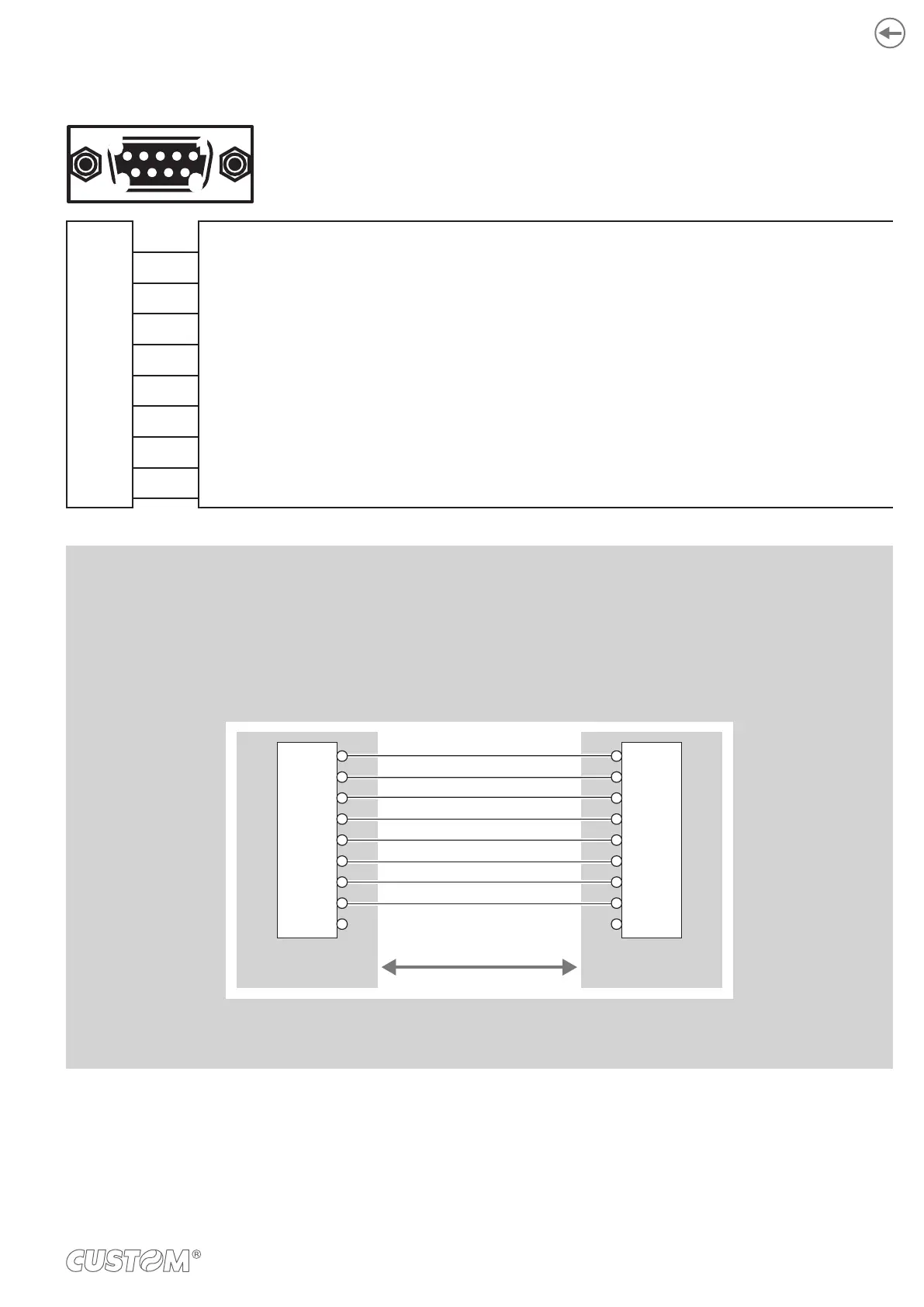
DEVICE > PC connection
The following picture shows an example of connection between the device and a personal computer using a 9 pin
RS232 serial connector:
DEVICE PC
DCD
RXD
TXD
GND
DSR
CTS
DTR
TXD
RXD
GND
DTR
RTS
DTRDSR
RTSCTS
DB9
1
2
3
4
5
6
7
8
9
DB9
1
2
3
4
5
6
7
8
9
When use a serial cable, we recommend the installation of a ferrite core on the power supply cable.
53