CVC TECHNOLOGIES, INC. CVC 310 OPERATION MANUAL
14 - 2
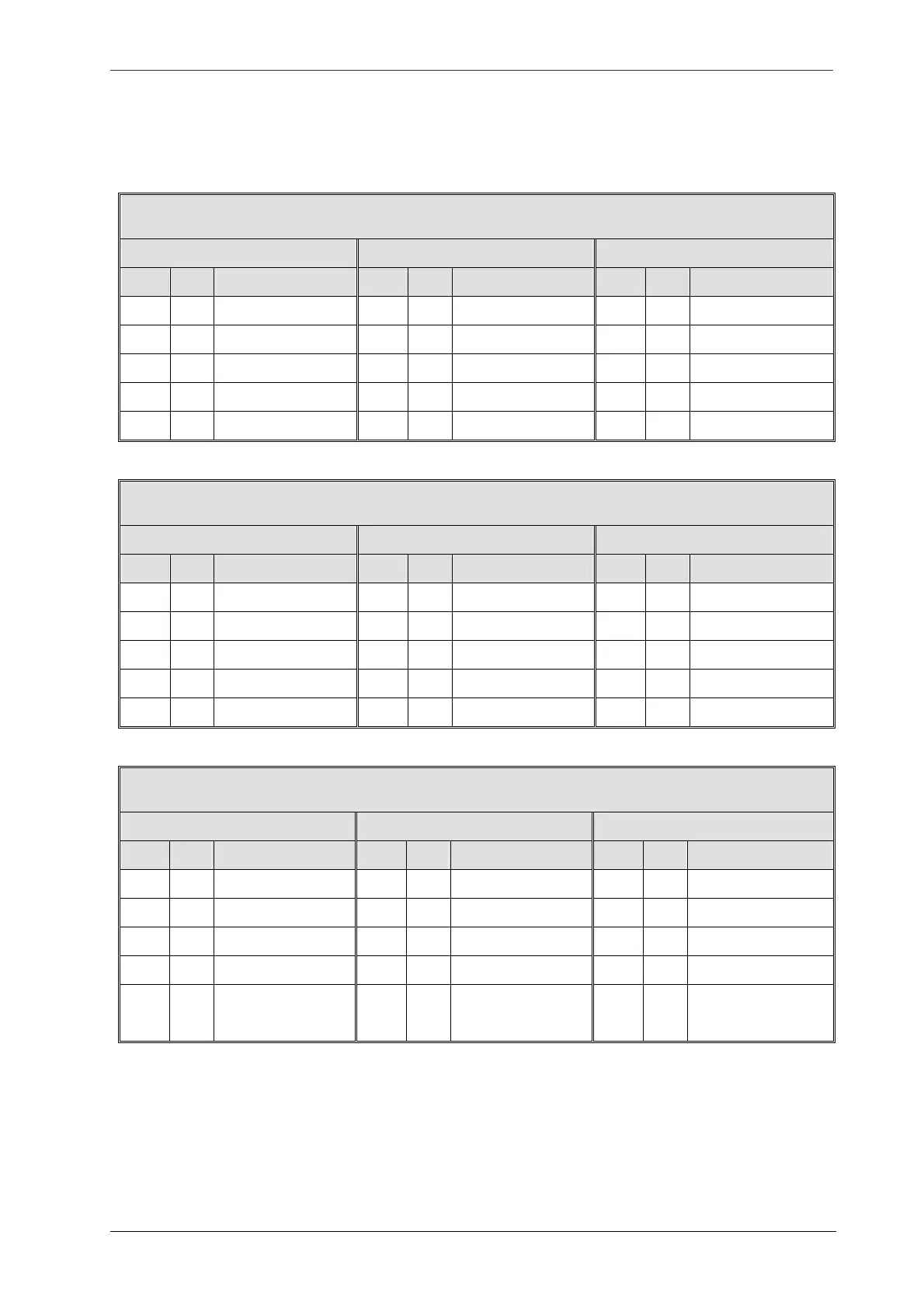
14.1 Pin Description
14.1.1 Side-Plate (Power Box)
※ Labeling Head A (Right, X2)
J29
Stepper Motor Coil
Labeling Head A (Right, X2)
Pin No.
Color Definition Pin No.
Color
Definition Pin No.
Color Definition
1 6 11
2 7 RED
A 12
3 8 YEL
A’ 13
4 9 ORG
B 14
5 10 BLU
B’ 15
J30
DC Motor Coil & AC 110 V Power
Pin No.
Color Definition Pin No.
Color
Definition Pin No.
Color Definition
1 6 BLK
Conveyor 11
2 WHT AC+(110V Printer) 7 WHT
Wrap Station 12
3 BLK AC- (110V Printer) 8 BLK
Wrap Station 13
4 9 WHT
Separator 14
5 WHT Conveyor 10 BLK
Separator 15
J33
DC Power & Signal Output
Pin No.
Color Definition Pin No.
Color
Definition Pin No.
Color Definition
1 WHT Turntable M+ 6 YEL
DC24 V 11
2 BLK Turntable M- 7 GRN
DC 24 VG 12
3 8 13 PPL Cylinder
4 9 14
5 10 15 RED
Head A (right, X2)
Printing signal output
DC 24V