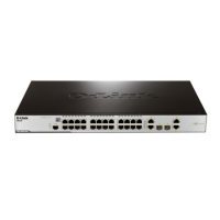
xStack® DES-3200 Series Layer 2 Ethernet Managed Switch CLI Reference Manual
21
2
Now that an access profile has been created, users must add the criteria the Switch will use to decide if a given frame should be
forwarded or filtered. We will use the config access_profile command to create a new rule that defines the criteria we want. Let’s
further specify in the new rule to deny access to a range of IP addresses through an individual port: Here, we want to filter any
packets that have an IP source address between 10.42.73.0 and 10.42.73.255, and specify the port that will not be allowed:
config access_profile profile_id 1 add access_id 1 ip source_ip 10.42.73.1 port 7 deny
We use the profile_id 1 which was specified when the access profile was created. The add parameter instructs the Switch to add
the criteria that follows to the list of rules that are associated with access profile 1. For each rule entered into the access profile,
users can assign an access_id that identifies the rule within the list of rules. The access_id is an index number only and does not
effect priority within the profile_id. This access_id may be used later if users want to remove the individual rule from the profile.
The ip parameter instructs the Switch that this new rule will be applied to the IP addresses contained within each frame’s header.
source_ip tells the Switch that this rule will apply to the source IP addresses in each frame’s header. The IP address 10.42.73.1
will be combined with the source_ip_mask 255.255.255.0 to give the IP address 10.42.73.0 for any source IP address between
10.42.73.0 to 10.42.73.255. Finally the restricted port - port number 7 - is specified.
Each command is listed, in detail, in the following sections:
create access_profile
Used to creat
e an access profile on the Switch and to define which parts of each incoming
frame’s header the Switch will examine. Masks can be entered that will be combined with the
values the Switch finds in the specified frame header fields. Specific values for the rules are
entered using the config access_profile command, below.
Purpose
c
reate access_profile [ethernet {vlan {<hex 0x0-0x0fff>} | source_mac <macmask> |
destination_mac <macmask> | 802.1p | ethernet_type} (1) | ip { vlan {<hex 0x0-0x0fff>} |
source_ip_mask <netmask> | destination_ip_mask <netmask> | dscp | [ icmp { type | code } |
igmp {type} | tcp { src_port_mask <hex 0x0-0xffff> | dst_port_mask <hex 0x0-0xffff> |
flag_mask [ all | { urg | ack | psh | rst | syn | fin } (1) ] } | udp { src_port_mask <hex 0x0-0xffff> |
dst_port_mask <hex 0x0-0xffff>} | protocol_id_mask<0x0-0xff> ] } (1) | packet_content_mask
{destination_mac <macmask> | source_mac <macmask> | c_tag <hex 0x0-0xffff> | s_tag
<hex 0x0-0xffff> | offset1 [l2 | l3 | l4] <value 0-31> <hex 0x0-0xffff> | offset2 [l2 | l3 | l4] <value
0-31> <hex 0x0-0xffff> | offset3 [l2 | l3 | l4] <value 0-31> <hex 0x0-0xffff> | offset4 [l2 | l3 | l4]
<value 0-31> <hex 0x0-0xffff> | offset5 [l2 | l3 | l4] <value 0-31> <hex 0x0-0xffff> | offset6 [l2 |
l3 | l4] <value 0-31> <hex 0x0-0xffff> | offset7 [l2 | l3 | l4] <value 0-31> <hex 0x0-0xffff> |
offset8 [l2 | l3 | l4] <value 0-31> <hex 0x0-0xffff> | offset9 [l2 | l3 | l4] <value 0-31> <hex 0x0-
0xffff> | offset10 [l2 | l3 | l4] <value 0-31> <hex 0x0-0xffff> | offset11 [l2 | l3 | l4] <value 0-31>
<hex 0x0-0xffff> } (1) ] | ipv6 {class | flowlabel | source_ipv6_mask< ipv6mask ::-
::FFF:FFFF:FFFF> [ tcp {src_port_mask <hex 0x0-0xffff> | dst_port_mask <hex 0x0-0xffff>} |
udp {src_port_mask <hex 0x0-0xffff> | dst_port_mask <hex 0x0-0xffff> } ] } ] profile_id <value
1-512>
Syntax
This
command is used to create an access profile on the Switch and to define which parts of
each incoming frame’s header the Switch will examine. Masks can be entered that will be
combined with the values the Switch finds in the specified frame header fields. Specific values
for the rules are entered using the config access_profile command, below.
Description
Parameters
ethernet Specifies that the Switch will examine the layer 2 part of each packet header.
vlan Specifies a VLAN mask. Only the last 12 bits of the mask will be considered.
source_mac <macmask> Specifies a MAC address mask for the source MAC address.
This mask is entered in a hexadecimal format.
destination_mac <macmask> Specifies a MAC address mask for the destination MAC
address.
802.1p Specifies that the Switch will examine the 802.1p priority value in the frame’s
header.
ethernet_type Specifies that the Switch will examine the Ethernet type value in each
frame’s header.
ip Specifies that the Switch will examine the IP fields in each frame’s header.
vlan Specifies a VLAN mask. Only the last 12 bits of the mask will be considered.
 Loading...
