ENGLISH
42
2. BLINKING:
GREEN: Communication in progress.
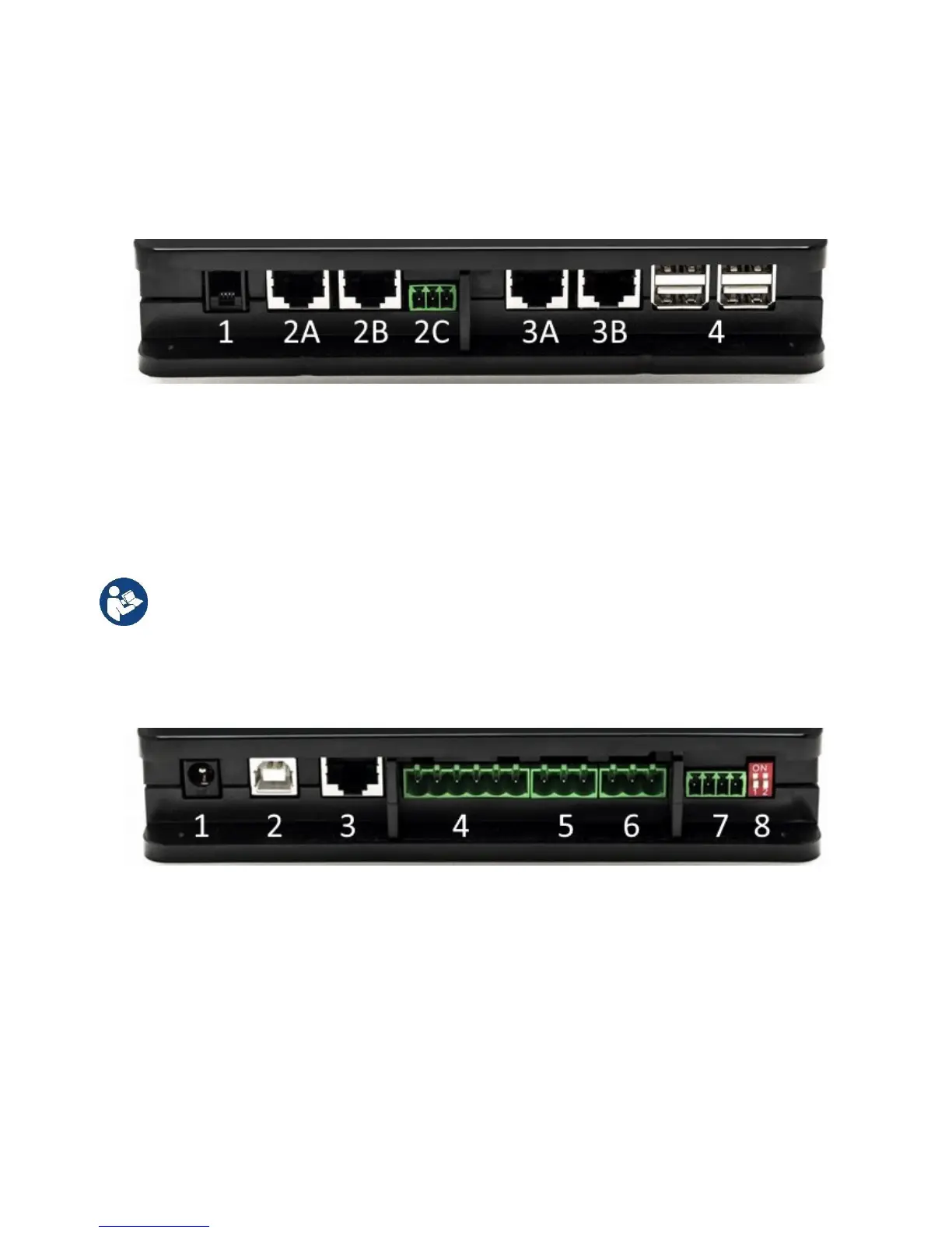
3.1.5 Rear View:
Note: For the connections of the products mentioned, see the dedicated section of this manual.
1. Serial Port.
2. Can Bus Port 1:
A for ADAC/MCE.
B for ADAC/MCE.
C for ACTIVE DRIVER PLUS.
3. Can Bus Port 2:
A for ADAC/MCE.
B for ADAC/MCE.
Note: The ports 2A, 2B, 2C are in parallel and it is possible to connect only identical devices.
The ports 3A, 3B, are in parallel and it is possible to connect only identical devices. If port
2C is used to connect an Active Driver Plus, it will not be possible to use ports 2A or 2B to
connect ADAC/MCE. In this case use the ports 3A or 3B.
4. USB Ports: EBOX/Expansions.
3.1.6 Front View:
1. Power supply / Power Jack.
2. USB Host (power supply only).
3. Ethernet Port: LAN cable connection.
4. I/O.
5. Relay A.
6. Relay B.
7. Modbus: Evoplus / Fire-fighting.
8. Dip Switch: Modbus Configuration..
3.1.7 Rear View:
1. Housing for DIN bar mounting bracket.
2. Holes for wall mounting fixtures.
3. Rubber feet for mounting on flat surface.
4. Housing for technical data plate.