– 8 –
Peripheral Connections
Peripheral connections can be made at these locations:
• The CAN network supports a group of devices that communicate over a pair of
signal wires connected parallel to each other. Each device on a CAN network must
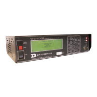
have a unique address. The CAN network port on the VFC-3000 controller is labeled
as Local Sensor (J2) on the rear of the controller. A CAN network port is provided on
the CAN distribution board inside the display.
• The DC I/O board has several input and output ports to control output states and
receive current input states.
• The auxiliary control port can interface with an uninterruptible power supply (UPS)
via an RS232 connection. This enables the VFC-3000 controller to inform operators of
current UPS states or errors.