Linea SWIR GigE Series Camera Connecting the Linea SWIR GigE Camera
15
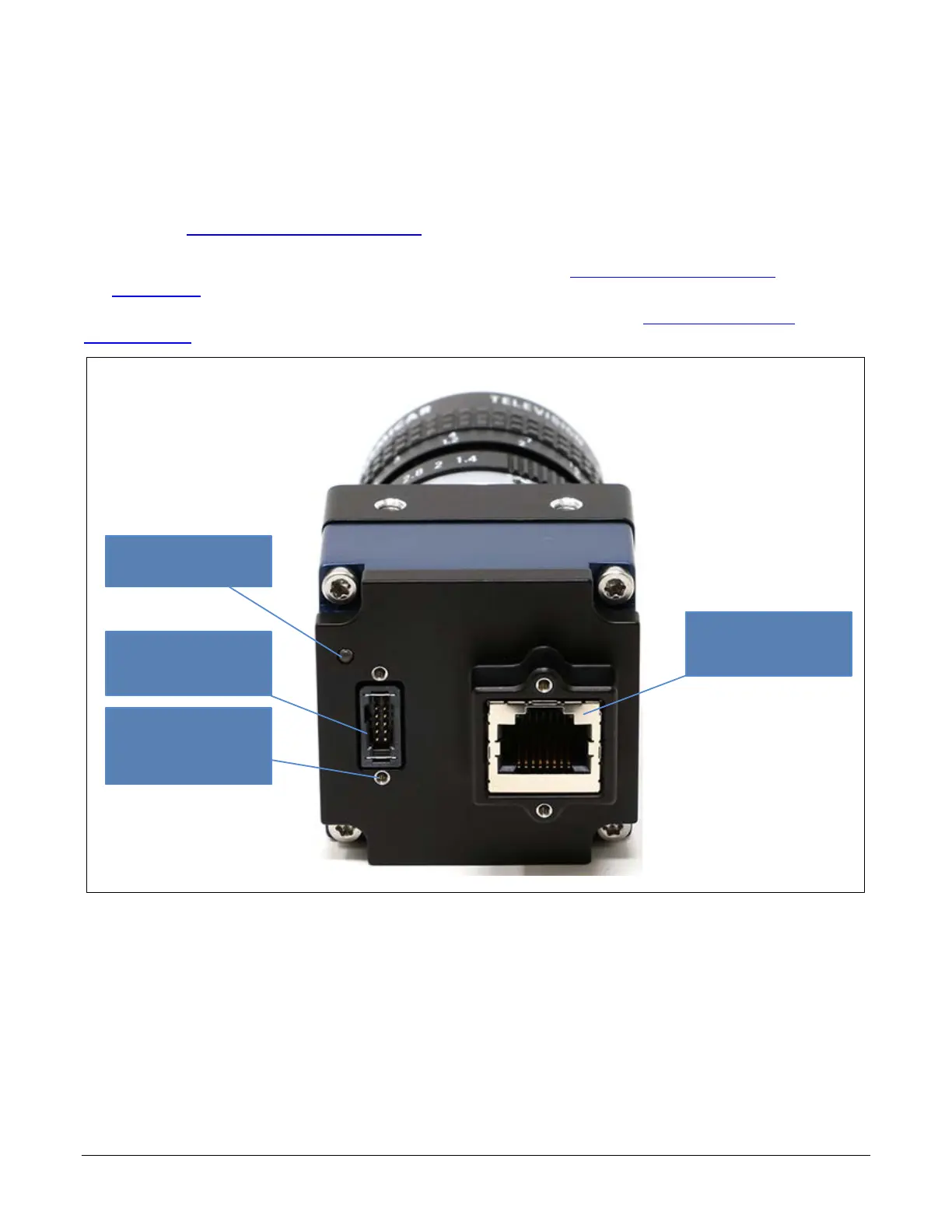
Connectors
The camera has two connectors.
• An RJ45 Ethernet connector for control and data transmitted between the camera and Gigabit
NIC. See Ruggedized Cable Accessories for secure cables.
• A 10-pin I/O connector for camera power, plus trigger, strobe and general I/O signals.
Teledyne DALSA provides an optional breakout cable (see Cable Assembly G3-AIOC-
BRKOUT2M).
The following figure shows the 10-pin connector and LED location. See Camera Mechanical
Specifications for connector and camera mounting details and dimensions.
Status LED
10-Pin
I/O and Power
Thumbscrew
Secured Cables
Supported
Ethernet
(supports POE)
Figure 5: Rear View with Labels

 Loading...


