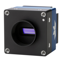
Linea SWIR GigE Series Camera Contents
5
Table of Figures
Figure 1: Camera Back View ........................................................................................ 7
Figure 2: Sapera Application Diagram ........................................................................... 9
Figure 3: Spectral Responsivity .................................................................................. 12
Figure 4: PRNU Derating Curve .................................................................................. 13
Figure 5: Rear View with Labels ................................................................................. 15
Figure 6: Status LED Colors ....................................................................................... 16
Figure 7: Status LED Color Sequence .......................................................................... 17
Figure 8: GigE Server Icon States .............................................................................. 20
Figure 9: GigE Server Tray Icon Menu......................................................................... 21
Figure 10: GigE Server Status Dialog .......................................................................... 21
Figure 11: Network Imaging Tool ............................................................................... 22
Figure 12: CamExpert ............................................................................................... 24
Figure 13: CamExpert Panes...................................................................................... 26
Figure 14: CamExpert Control Buttons ........................................................................ 27
Figure 15: Camera Information Features ..................................................................... 28
Figure 16: Power up Mode Menu ................................................................................ 31
Figure 17: Sensor Control Features ............................................................................ 32
Figure 18: I/O Control Features ................................................................................. 36
Figure 19: I/O Module Block Diagram ......................................................................... 42
Figure 20: Counter and Timer Features ....................................................................... 44
Figure 21: Counter and Timer Block Diagram ............................................................... 48
Figure 22: Counter Start Source = OFF ....................................................................... 48
Figure 23: Counter Start Source = CounterEnd ............................................................ 49
Figure 24: CounterStartSource = EVENT ..................................................................... 49
Figure 25: CounterStartSource = Signal ...................................................................... 50
Figure 26: CounterStartSource = Line......................................................................... 50
Figure 27: Advanced Processing Features .................................................................... 51
Figure 28: Black Acquisition Histogram ....................................................................... 58
Figure 29: Bright Acquisition Histogram ...................................................................... 59
Figure 30: Advanced Processing Features .................................................................... 60
Figure 31: Set Correction Mode Off ............................................................................. 61
Figure 32: Bare Image Line Profile of a White Uniform Object ........................................ 61
Figure 33: Sensor Control category ............................................................................ 62
Figure 34 A histogram of a black image. .................................................................... 63
Figure 35: FFC Calibration Selection ........................................................................... 63
Figure 36: PRNU Correction ....................................................................................... 64
Figure 37: Line profile of a white uniform target after PRNU calibration. .......................... 65
Figure 38: Cycling Preset .......................................................................................... 66
Figure 39: Image Format Features ............................................................................. 70
Figure 40: How Binning Works ................................................................................... 72
Figure 41: Acquisition and Transfer Features ............................................................... 73
Figure 42: Camera Circular Frame Buffer .................................................................... 77
Figure 43: GigE Vision Transport Layer Features .......................................................... 79
Figure 44: File Access Features .................................................................................. 85
Figure 45: File Access Menu....................................................................................... 87
Figure 46: DHCP Network .......................................................................................... 90
Figure 47: Persistent IP Network ................................................................................ 91
Figure 48: Mechanical ............................................................................................... 92
Figure 49: Sensor Alignment Reference ...................................................................... 93
Figure 50: I/O Connector 3D View .............................................................................. 94
Figure 51: I/O Connector ID ...................................................................................... 95
Figure 52: Samtec ISDF-05-D-M Mating Connector ....................................................... 96

 Loading...