19. PositionthewiresasshowninFigure4-67MotorWirePositionandFigure4-68IGVMotorWires
Connected.
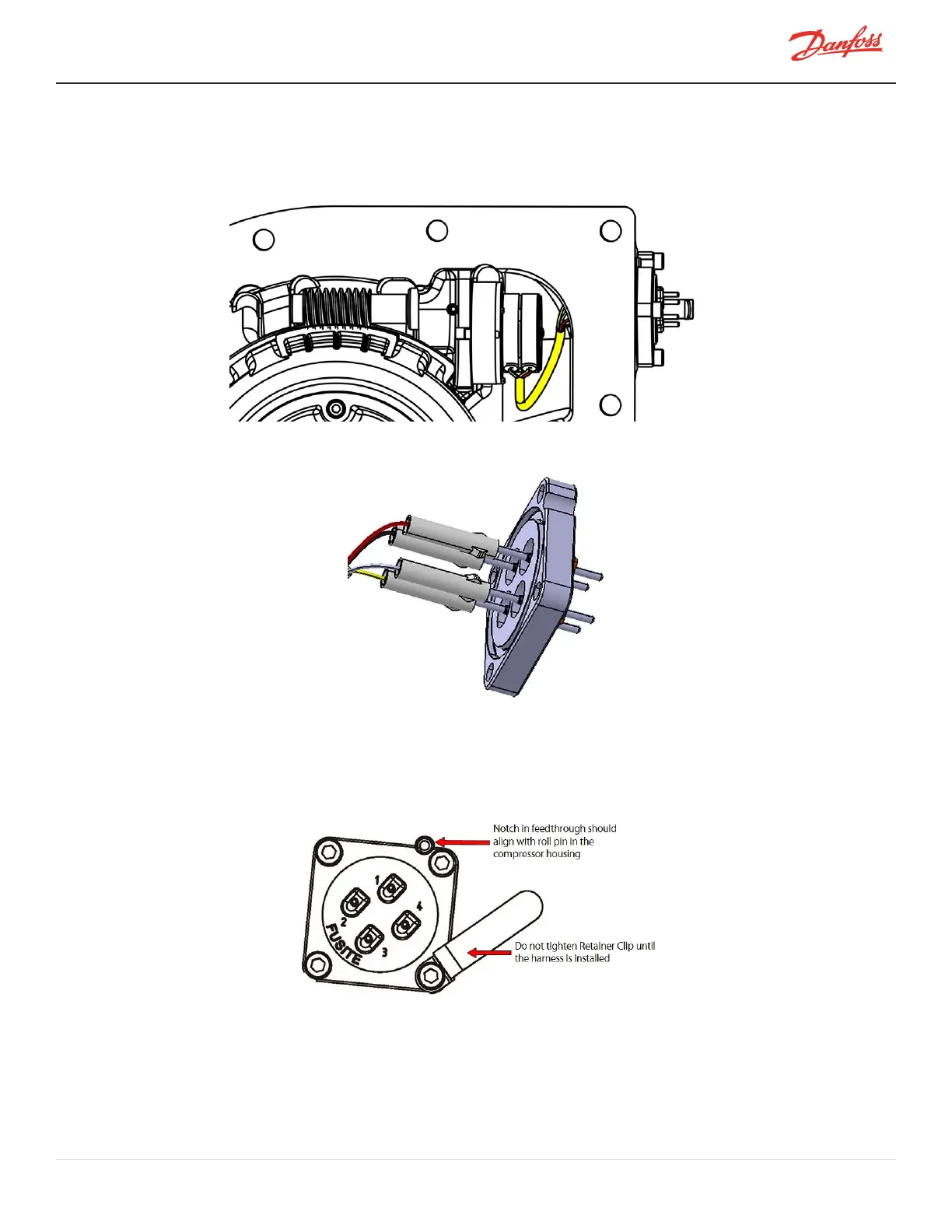
Figure 4-67 Motor Wire Position
Figure 4-68 IGV Motor Wires Connected
20. InstalltheFeedthroughusingthefour(4)M5x16fastenersandinstalltheIGVMotorCableRetainerClip
underoneofthefasteners.Tightenonlythree(3)ofthefastenersto5Nm(44in.lb.)whileleavingthe
fourthfastenerwiththeretainerclipslightlyloose.RefertoFigure4-69FeedthroughOrientation.
Figure 4-69 Feedthrough Orientation
21. Ifavailable,testthemotoroperationwithasteppermotordriver.OperationoftheIGVcanalsobe
testedusingtheSMTdrivingtheIGVmanually(oncetheIGVhasbeenmountedonthecompressor).
22. CleanthematingsurfacesofboththecompressorandIGV.
23. Clean,lubricate,andinstalltheIGVHousingO-ring.
M-SV-001-EN Rev. H-1/23/2023 Page 93 of 294