6. InstalltheDCBusBarstotheSCRs.RefertoSection4.21.3DCCapacitorBusBarAssemblyRemovaland
Installationonpage168.
7. Installthetopcovers.RefertoSection4.1CompressorCoversonpage52.
8. Returnthecompressortonormaloperation.
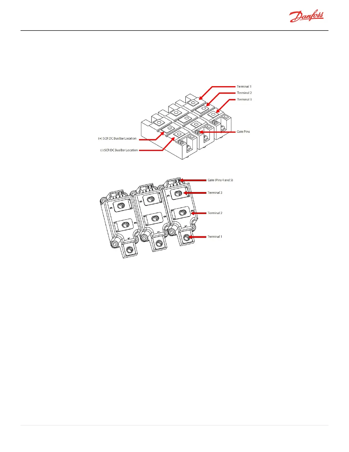
Figure 4-143 SCR Terminals - Two-Hole Mount
Figure 4-144 SCR Terminals - Four-Hole Mount
4.18.2.2 Diodes Verification - Four-Hole Mount
1. IsolatecompressorpowerasdescribedinSection1.8ElectricalIsolationonpage22.
2. RemovetheSoftStart.RefertoSection4.14.3SoftStartRemovalandInstallationonpage117.
3. RemovetheACmainsinputterminalsandbusbars.RefertoSection4.11.23-PhaseMainVoltageInput
TerminalBlockRemovalandInstallationonpage102.
4. RemovetheCapacitorAssembly.RefertoSection4.21.3DCCapacitorBusBarAssemblyRemovaland
Installationonpage168.
5. Usingamultimetersetfordiodemeasurements,placetheblack(-)leadonterminal1oftheSCRand
placethered(+)leadonterminal3.Themeasuredvalueshouldbebetween0.3Vand0.45V.Referto
Figure4-143SCRTerminals-Two-HoleMountandFigure4-144SCRTerminals-Four-HoleMount.
6. Allotherterminalsshouldreadinfinityoropeninbothdirections(polarity).RefertoTable4-28SCR
DiodeValuesonpage144.
7. PerformthistestforeachSCR.
8. InstalltheCapacitorandDCBusAssemblyandverifytheSCRTemperatureSensorCableisnotpinched.
RefertoSection4.21.4.4DCCapacitorBusBarAssemblyInstallation-TTS/TGS/TTH/TGH(Except
TTS300/TGS230)onpage174.
M-SV-001-EN Rev. H-1/23/2023 Page 143 of 294