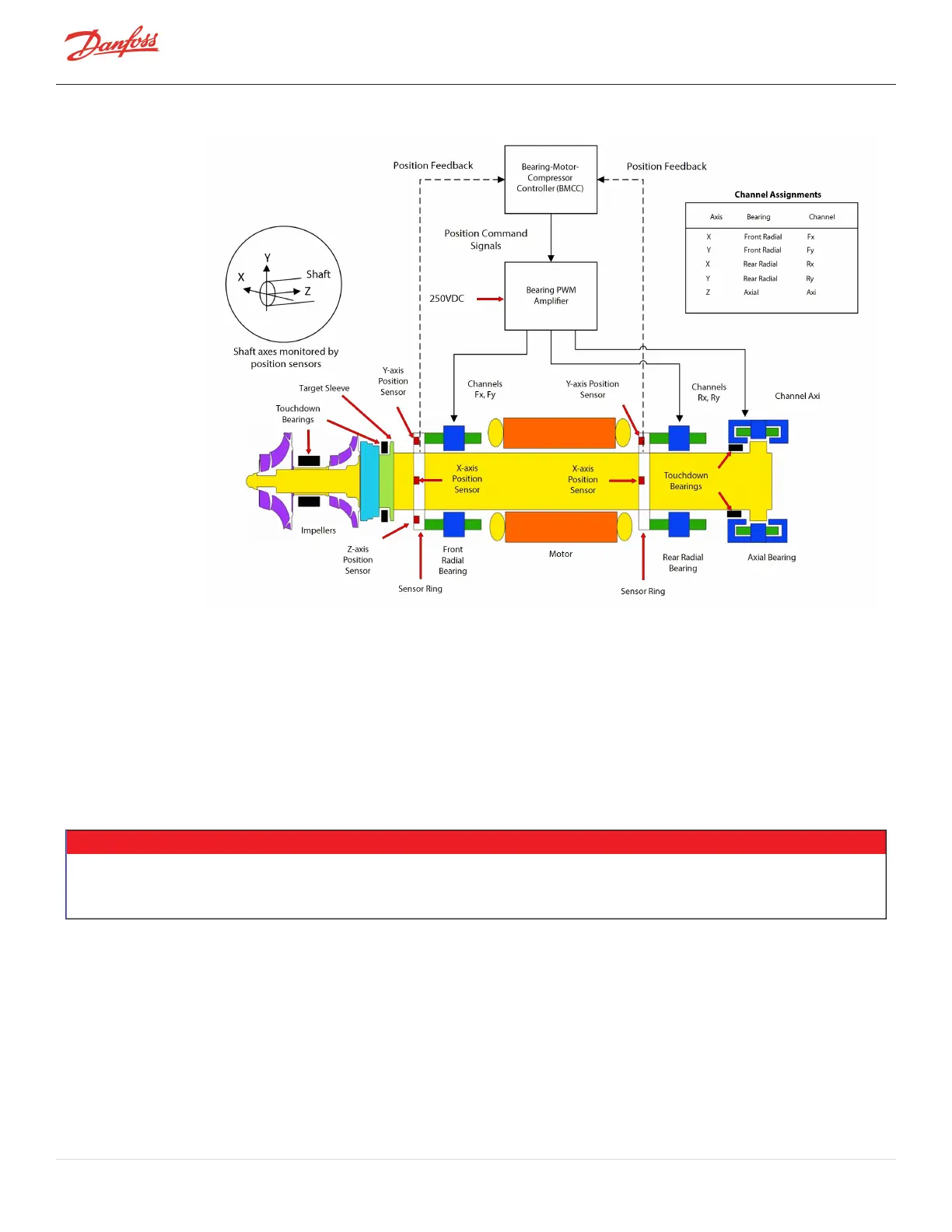
Figure 4-252 Bearing Control Signal Flow
4.28.2 PWM Connections
J1ontheBackplaneisthePWMconnectionport.ThePWMheatsinkissecuredwithfastenerstothecompressor
housingbelowtheBackplane.
The6-pin/wireconnectstotherear(left)bearingpowerfeedthrough.The4-pin/wireconnectstothefront(right)
bearingpowerfeedthrough.RefertoFigure4-251PWMonpage225foranillustrationofaMajorRevision"F"and
latercompressor.
4.28.3 PWM Verification
NOTE
l
AfaultyPWMAmplifiermaybetheresultofabearingfailureandmaycauseafailureofthePottedDC-DCresultingina
blownF1fuseontheClosed-TopSoftStart
l
IfaPWMAmplifierisfoundtobefaulty,thebearingactuatorcoils,DC-DC,andF1Fusemustalsobeverified
SeveralverificationmethodsareavailableforthePWM:
l
VerifyifthePWMisdrainingenergy
l
Verifyfunctionalityofthefive(5)outputchannels
l
Verifyfunctionalityofthefive(5)diodesets
Page 226 of 294 - M-SV-001-EN Rev. H 1/23/2023