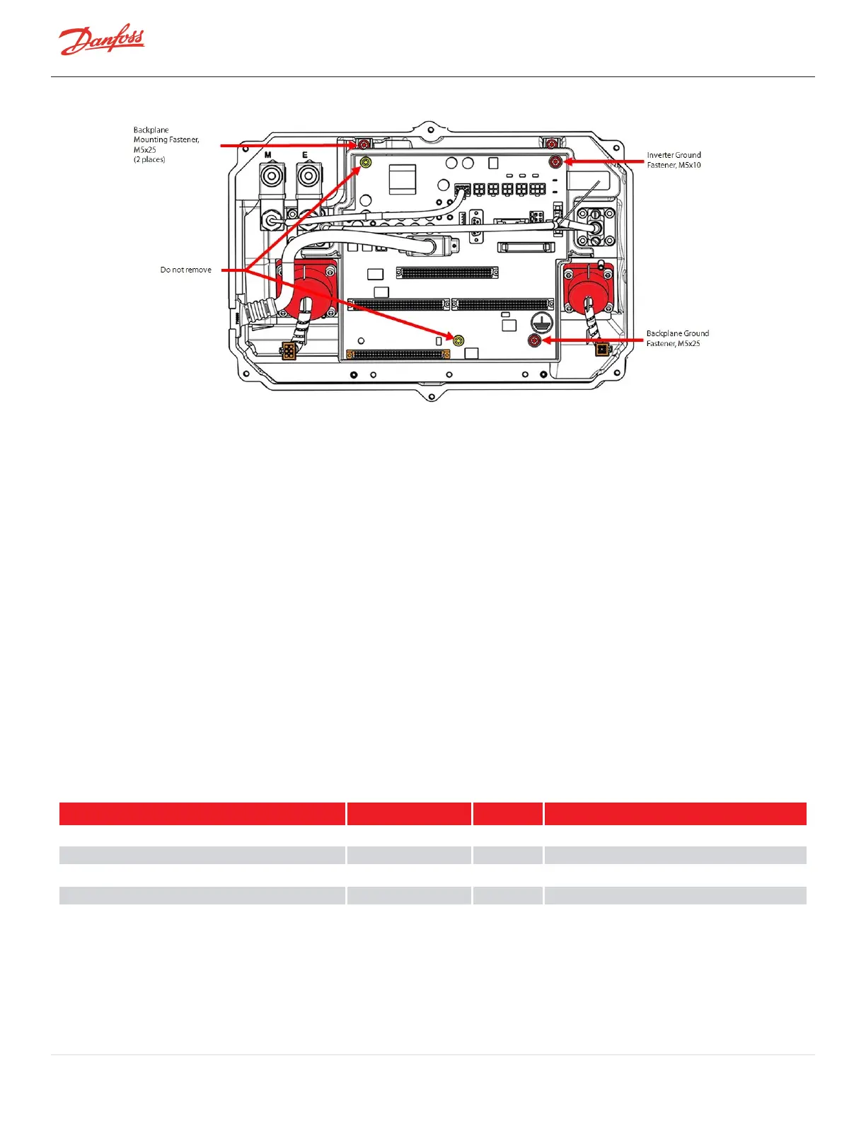
Figure 4-242 Removing the Backplane
10. RemovetheBackplaneFramefromthecompressorhousing.
4.25.3.2 Backplane Installation
1. AligntheBackplanewiththemountingholes,ensuringthecavitytemperaturesensorconnectoris
available.
2. InsertandtorquethefastenersatthetopoftheBackplaneFrameto3Nm(27in.lb.).
3. InsertandtorquetheBackplaneGroundfasteneratthebottomrightoftheBackplaneto3Nm(27
in.lb.).
4. Installallconnectorstotheirappropriatelocations.
5. RemovetheInverterGroundfastenerfromtoprightoftheBackplane.
6. ConnecttheInvertergroundringtotheInverterGroundScrewandtorquethefastenerattoprightof
theBackplaneto3Nm(27in.lb.).
7. InstalltheBearingPWMAmplifier,BMCC,andSerialDriver.
8. InstalltheServiceSideCover.RefertoSection4.1.3.1ServiceSideCoverRemovalandInstallationon
page54.
9. Returnthecompressortonormaloperation.
4.25.3.3 Backplane Torque Specifications
Table 4-43 Backplane Torque Specifications
Description Nm Ft.Lb. In.Lb.
BackplaneMounting/Groundfastener,M5x10 3 - 27
InverterGroundfastener,M5x25 3 - 27
PWMMounting/heatsinkfastener,M5x10 4.5 - 40
Coverfastener,M5x15 1.5 - 13
Page 216 of 294 - M-SV-001-EN Rev. H 1/23/2023