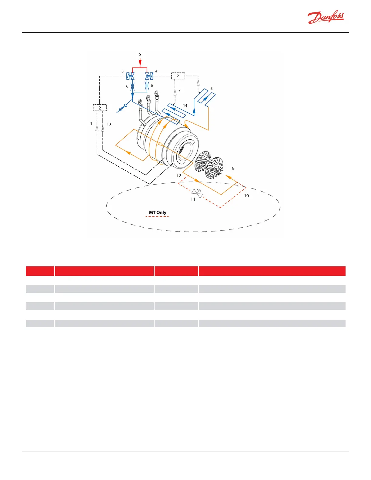
Figure 2-5 Compressor Cooling Path - TTS300/TGS230
Table 2-3 Compressor Cooling Path - (TTS300/TGS230)
No. Description No. Description
1 FromMotorWindingTempSensor 8 SCRManifold
2 BMCC 9 Motor/RotorCoolingGas
3 SolenoidM 10*MTOnly Coolingpathre-entersatthesuctionlineofthechiller
4 SolenoidE 11*MTOnly PressureRegulatingValve
5 LiquidRefrigerantInlet 12*MTOnly Coolingpathredirectsoutsideofthecompressor
6 Orifice 13 FromMotorCavityTemp.Sensor
7 FromInverterTempSensor 14 Inverter
2.3 Capacity Control
Capacitycontrolofthecompressorisachievedprimarilybyspeedmodulation.Whenunloading,thecompressor’s
firstactionistoreducespeedtoslightlyabovetheminimum(surge)speedforthepressureratiopresentatthetime.
Furtherreductionincapacityandanincreaseinshaft/impellerstabilitycanbeachievedbyclosingtheIGVs.These
arevariableanglevanesinstalledinthesuctioninletaheadofthefirst-stageimpeller.Theseguidevanesrestrictthe
refrigerantfromenteringtheimpellerinlet,aswellasimpartinga“pre-swirl”oftherefrigerantinthedirectionof
impellerrotationtoincreaseenergyefficiencyduringpartloadoperation.
M-SV-001-EN Rev. H-1/23/2023 Page 37 of 294