12. IfaPottedDC-DCConverterisbeinginstalled,cleanthesurfaceoftheInverterHeatSinkPlateandthe
DC-DCConverter.TheOpen-FrameDC-DCConverterdoesnotrequireheatsinkpaste.
13. InstalltheDC-DCConverter.RefertoSection4.24.3DC-DCRemovalandInstallationonpage206.
14. InstalltheDCbusBarandCapacitorAssemblyandSnubberCapacitors.RefertoSection4.21.4.3DC
CapacitorBusBarAssemblyInstallation-TTS300/TGS230onpage174.
15. InstalltheTerminalblockandFuseassemblies.RefertoSection4.11.23-PhaseMainVoltageInput
TerminalBlockRemovalandInstallationonpage102.
16. InstallthemainsinputcablestotheTerminalBlockandtorqueto20Nm(15ft.lb.).ConnecttheSCR
GatecableharnesstotheSCRsnotingitsorientation.
17. ConnecttheSCRGatecableharnesstotheSCRsnotingitsorientation.
4.22.6.4 Compressor Specific Inverter Installation Steps - TTS/TGS/TTH/TGH (Except TTS300/TGS230)
1. CleantheO-ringgrooveinthemaincompressorhousingwithalint-freecloth.
2. ApplyO-lubeandinstalltheInverterO-ringinthecompressorhousinggroove.
3. RemovethebackingmaterialfromtheInverterCoolingManifoldofthenewInverter.Usecautionto
notdamagethebottomsealingsurfaceoftheInverter.
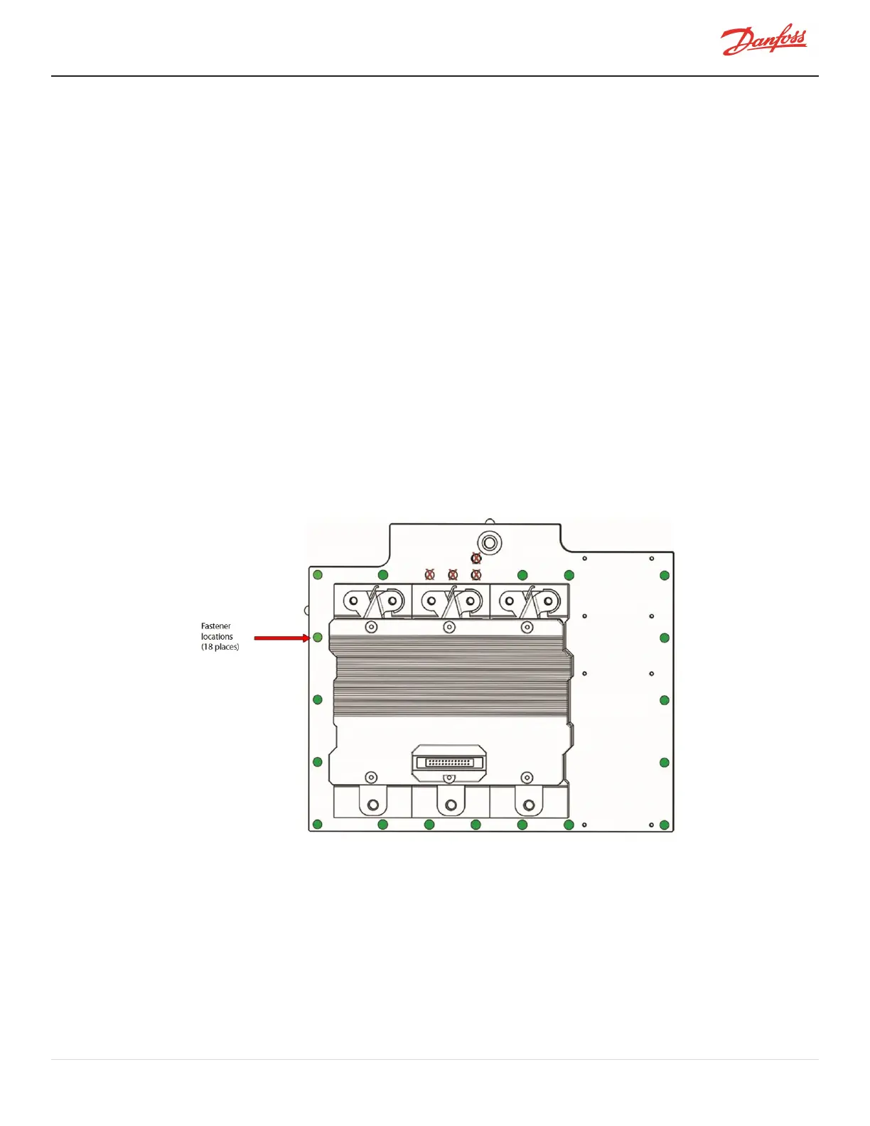
4. Installthe18M6x30fastenersintotheInverterassemblywiththeexceptionofthefour(4)M6x35SCR
Manifoldfastenersandcarefullylowertheassemblyontothecompressorhousing.Usetheinstalled
fastenerstoproperlylineuptheInverter.RefertoFigure4-209InverterFastenerLocations-
TTS/TGS/TGH(ExceptTTS300/TGS230)onpage187.
Figure 4-209 Inverter Fastener Locations - TTS/TGS/TGH (Except TTS300/TGS230)
5. OncetheInverterisinplace,finger-tightentheInverterfastenersinadiagonalpatternandtorqueto3
Nm(27in.lb.)onthefirstpass,thento7Nm(62in.lb.)onthesecondpass.
6. InstalltheSCRCoolingManifoldandSCRs.RefertoSection4.19.5SCRCoolingManifoldSpecific
InstallationSteps-TTS/TGS/TTH/TGH(ExceptTTS300/TGS230)onpage160.
7. Installthethree(3)CopperTubesandtorquetheM8x70fastenerstospecification.
8. InstalltheDC-DCConvertertotheInvertercoolingmanifold.RefertoSection4.24.3DC-DCRemoval
andInstallationonpage206.
9. Verifythecompressorcableharness(andtheSCRTemperatureSensorCable-ifapplicable)isproperly
placedacrossthecoolingmanifold.
M-SV-001-EN Rev. H-1/23/2023 Page 187 of 294