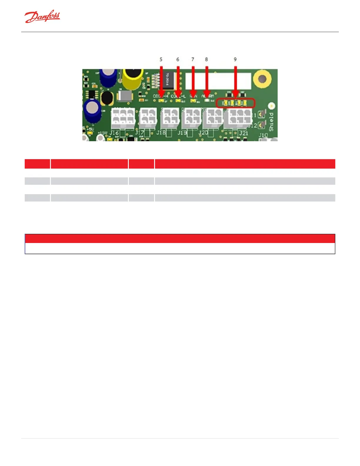
Figure 4-241 Backplane LED Locations - Right Side
Table 4-41 Backplane LED Locations
No. Component No. Component
1 D2:+17VDC 6 D10:Cool-Lpowertosolenoid
2 D1:+5VDC 7 D11:Runcontactisclosedwhenon
3 D6:+15VDC 8 D12:CompressorStatus:Redindicatesalarmorreset,Greenindicatesnormal
4 D9:+24VDC 9 D13-D16:IGVStepperMotorIndicator;flickerwhenoperating
5 D7:Cool-Hpowertosolenoid
4.25.2.2 Backplane Verification
NOTE
Thetest-pointLEDsareONifANYvoltageispresent.Thetestpointsmustbemeasuredtodeterminetheactualvoltage.
1. RemovetheServiceSideCover.RefertoSection4.1.3.1ServiceSideCoverRemovalandInstallationon
page54.
2. Withmainpoweron,usingamultimetersetforDCvoltagemeasurements,placethemultimeterleads
intheBackplanetestpointsasdefinedinFigure4-239BackplaneTestPointsonpage213.Table4-42
BackplaneTestPointValuesonpage215.
3. Isolatecompressorpower.
4. UnplugconnectorsJ4andJ24fromtheBackplane.
5. Usingamultimetersetforresistancemeasurements,placethemultimeterleadsintheBackplanetest
pointsasdefinedinFigure4-239BackplaneTestPointsonpage213.Theresultsshouldbegreater
thantheresistancespecifiedinTable4-42BackplaneTestPointValuesonpage215.
6. IfoneofthetestpointsdoesnotoutputtheexpectedvoltageandtheHV+and+24Vtestpoints
outputthecorrectvoltage,removetheSerialDriver,BMCC,andPWM.
7. PlugconnectorsJ4andJ24totheBackplane.
8. RepeatStep2.Ifthevoltagesareasexpected,theBackplaneisfunctioningcorrectlyandnotthecause
oftheenergydrain.
Page 214 of 294 - M-SV-001-EN Rev. H 1/23/2023