Bearing Sensor Cable Installation:
1. Ensurethatallconnectorsarecleanandfreeofgreaseandsiliconegel.
2. FortheFrontBearingSensorCable,refertoSteps3-5;fortheRearBearingSensorCable,refertoSteps
6-8.
3. Installthe9-pinconnectorattheFrontBearingSensorFeedthroughandtorquethefastenersto0.5Nm
(0.4ft.lb.;4.4in.lb.).
4. Applyathincoatingofdielectricgreasetotheexteriorofthebearingsensor9-pinconnectorwhereit
meetsthefeedthroughtosealfrommoistureingress.
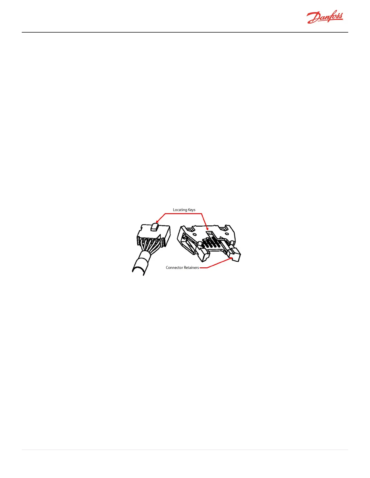
5. InstallthecabletoJ10ontheBackplane.Ensurethatplugisinsertedincorrectpolarity.Refertothe
locatingkeysontheplugandslotsintheconnector(TheFrontlocatingkeyshouldbeattheleftofthe
J10Backplaneclip.).Gentlysqueezetheconnectorretainerstosnaptheconnectorsinplace.
6. Installthe9-pinconnectorattheRearBearingSensorFeedthroughandtorquethefastenersto0.5Nm
(0.4ft.lb.;4.4in.lb.).
7. InstallthegroundwiretoJ11orJ12ontheBackplane.
8. InstallthecabletoJ9ontheBackplane.Ensurethatplugisinsertedincorrectpolarity.Refertothe
locatingkeysontheplugandslotsintheconnector(TheRearlocatingkeyshouldbeatthetopofthe
J9Backplaneclip.).Gentlysqueezetheconnectorretainerstosnaptheconnectorsinplace.Referto
Section4.30.3BearingSensorVerification.
Figure 4-264 Bearing Cable Orientation
9. InstalltheServiceSideCover.RefertoSection4.1.3.1ServiceSideCoverRemovalandInstallationon
page54.
10. Returnthecompressortonormaloperation.
11. Verifysensorcablefunctionalitybyperformingabearingcalibration.RefertoSection5.3Bearing
Calibrationonpage263.
4.30.5 Bearing Sensor Feedthrough Removal and Installation
ThefollowingprocedurewillcontainthesamestepsforeithertheFrontorRearBearingSensorFeedthrough.
4.30.5.1 Bearing Sensor Feedthrough Removal
1. Isolatecompressorpower.
2. RemovetheServiceSideCover.RefertoSection4.1.3.1ServiceSideCoverRemovalandInstallationon
page54.
3. WaitfortheLEDsontheBackplanetoturnoff.
4. Isolatethecompressorandrecovertherefrigerantaccordingtoindustrystandards.RefertoSection3.1
RefrigerantContainmentonpage41.
5. RemovetheServiceSideCover.RefertoSection4.1.3.1ServiceSideCoverRemovalandInstallationon
page54.
M-SV-001-EN Rev. H-1/23/2023 Page 239 of 294