6. Removethebearingsensorcablefromthe9-pinfeedthrough.RefertoFigure4-265BearingSensor
FeedthroughRemoval(Rear(Left)Shown).
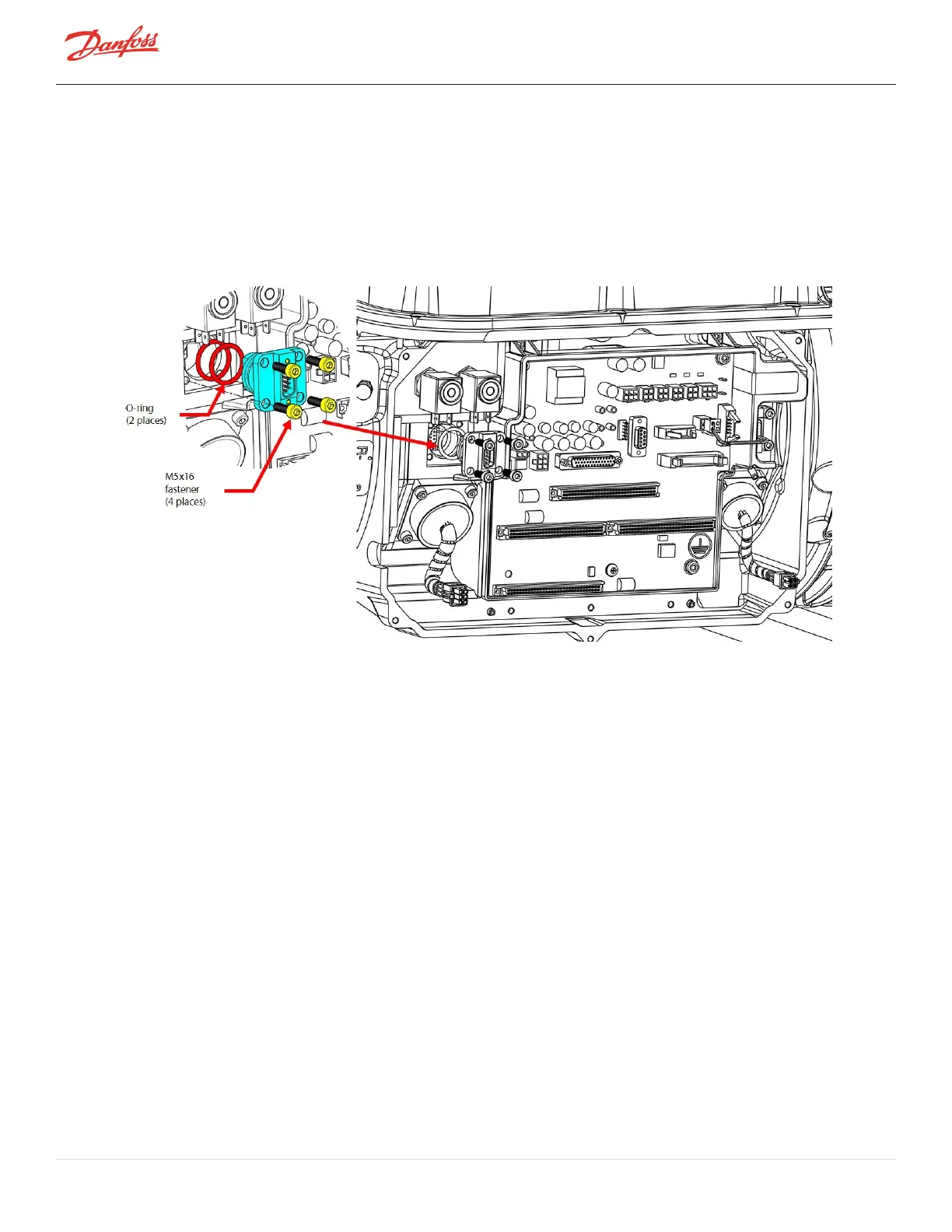
7. Usingahexsocket,removethefour(4)M5x16fastenersthatsecurethe9-pinfeedthrough.Referto
RefertoFigure4-265BearingSensorFeedthroughRemoval(Rear(Left)Shown).
8. Carefullyremovethe9-pinfeedthrough.Itmaybenecessarytouseneedle-noseplierstograspthe
feedthrough.Donotprythefeedthroughoutofthehousing.
Figure 4-265 Bearing Sensor Feedthrough Removal (Rear (Left) Shown)
4.30.5.2 Bearing Sensor Feedthrough Installation
1. Usingalint-freecloth,cleanthematingsurfaceonthecompressorhousing.
2. VerifythatthenewO-ringsand9-pinfeedthroughareclean.Ifnot,wipeoffanycontaminantswitha
lint-freecloth.
3. ApplyO-lubeoneachofthenewO-rings.
4. InstallthenewO-ringsontothenew9-pinfeedthrough.
5. Installthenew9-pinfeedthrough.
6. Securethefeedthroughwiththefour(4)M5x16fasteners.Finger-tightenandthenfollowthetorque
sequenceshowninFigure4-266BearingSensor9-PinFeedthroughConnectorTorqueSequenceon
page241andtorqueto3Nm(2.2ft.lb.).Torquethefastenersafinaltimeto5Nm(3.7ft.lb.).
Page 240 of 294 - M-SV-001-EN Rev. H 1/23/2023