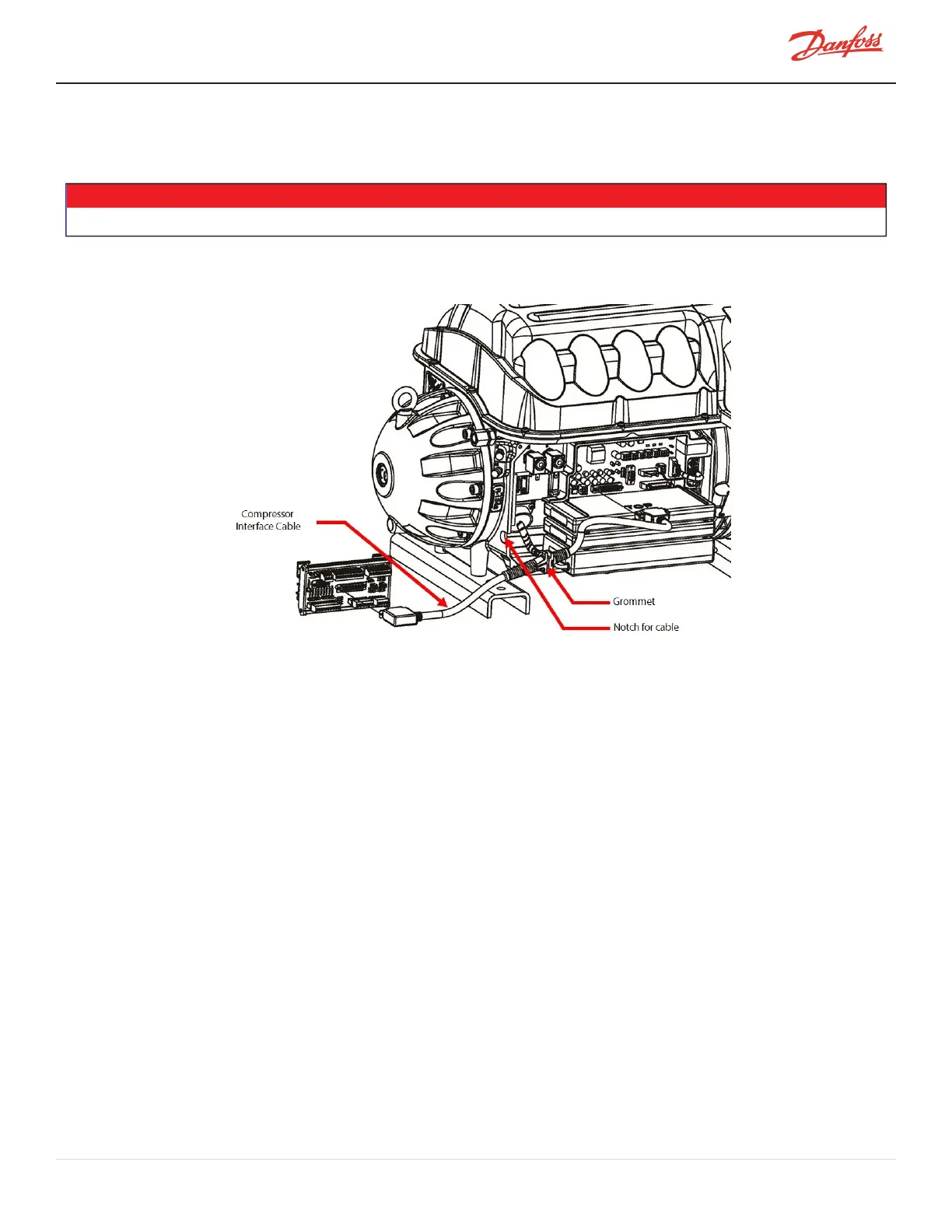
4.4 Compressor Interface Cable
TheCompressorInterfaceCableconnectsthecompressortotheCIM.RefertoFigure4-20CompressorInterface
Cable.
NOTE
Theothercableshavebeenremovedforclarity.
Figure 4-20 Compressor Interface Cable
4.4.1 Compressor Interface Cable Verification
Ifanycommunicationproblemsexist,verifytheintegrityofthecableassembly.Thiscanbeaccomplishedby
performingacontinuitytestateachcorrespondingpin.
4.4.2 Compressor Interface Cable Removal and Installation
4.4.2.1 Compressor Interface Cable Removal
1. Isolatecompressorpower.
2. Waitforthegreenlight(D9)ontheCIMtoturnoff.
3. RemovetheServiceSideCover.RefertoSection4.1.3.1ServiceSideCoverRemovalandInstallationon
page54.
4. WaitfortheBackplaneLEDstoturnoff.
5. Useaflat-bladescrewdrivertodisengagetheconnectorscrewsfromtheBackplane.
6. DisengagetheconnectorthumbscrewsfromtheCIM.
7. Removethecablebygraspingeachconnector(J6onCIMandJ7onBackplane)andpullingawayfrom
theboardconnectors.
4.4.2.2 Compressor Interface Cable Installation
1. InstallthecableintotheJ6connectorontheCIMandtheJ7connectorontheBackplane.
2. Tightentheconnectorstosecurethecable.
M-SV-001-EN Rev. H-1/23/2023 Page 65 of 294