10. RemovetheOrificeCoolingValvesfromthecompressorhousingusinga15/16"socket.
11. DiscardtheoldO-rings.
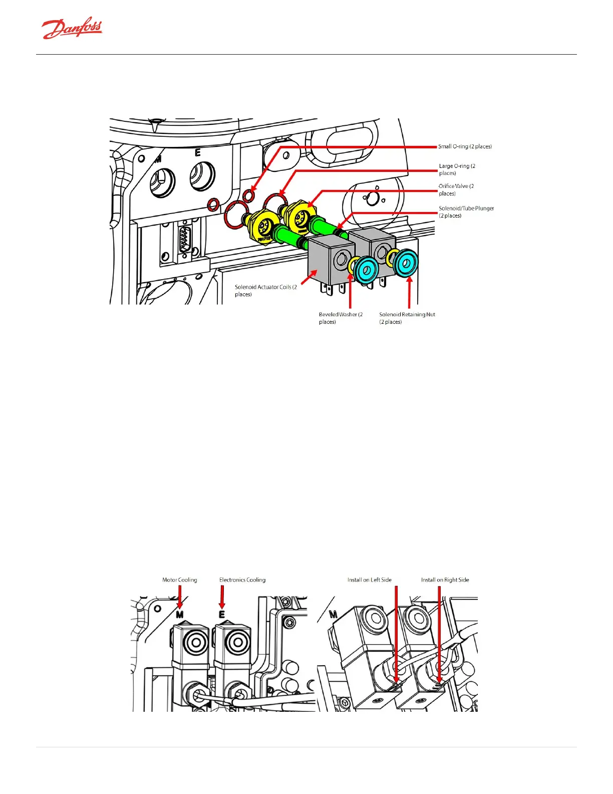
Figure 4-35 Solenoid Component Removal
4.6.4.2 Solenoid and Actuator Installation
1. Ensurethatallcomponentsandthreadsareclear,clean,andoilfree.
2. LubricatethesmallandlargenewO-ringswithO-ringlubricantandinstallthemontheCoolingValve
Assemblies.
3. InstallthenewOrificeBodiesintothecorrectcoolingpassagebasedontheinformationobtainedin
theremovalinstructions.
4. TightentheOrificeBodieswitha15/16"socketandtorqueto7Nm(62in.lb.).
5. ApplyO-ringlubricanttotheo-ringsontheplungerassemblies.
6. Checkthattheplungermovesfreelybyexercisingactionofspringbyhand~10cycles.
7. InsertthePlungerAssembliesintotheOrificeBodiesandengagethefirstfewthreadsbyhand.
8. TightenthePlungerAssembliesusingasix-point13mmdeepsocketandtorqueto4Nm(35in.lb.).
9. Leaktestandevacuatecompressorinaccordancewithstandardindustrypractices.
10. Installthesolenoidcoilsontotheplungerassembliesinthecorrectorientationaspreviouslynotedin
theRemovalinstructions.RefertoFigure4-36SolenoidActuatorCoilPosition.
Figure 4-36 Solenoid Actuator Coil Position
Page 76 of 294 - M-SV-001-EN Rev. H 1/23/2023