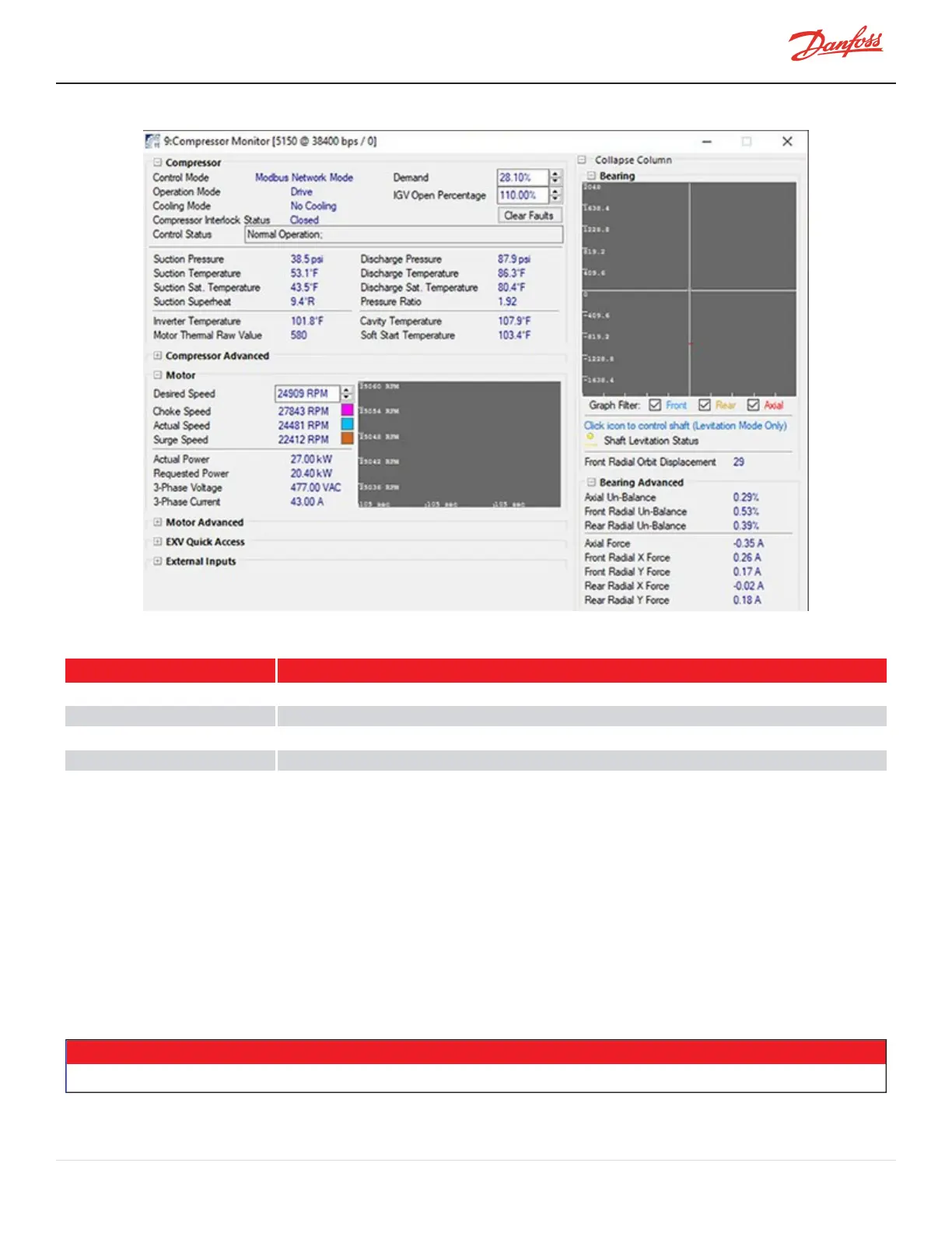
Figure 4-258 Compressor Monitor Tool
Table 4-46 Bearing Amperage Nominal Ranges
Bearing Position Force Range
AxialForce -1.5to1.5Amp(TTS300&TGS230=-2to0Amp)
FrontXForce -1.5to1.5Amp
FrontYForce -1.5to1.5Amp
RearXForce -1.5to1.5Amp
RearYForce -1.5to1.5Amp
4.29.4 Bearing Power Feedthrough Removal and Installation
Thestepsdepictedinthissectionwillapplytoeitherthefrontorrearfeedthrough.
4.29.4.1 Bearing Power Feedthrough Removal
1. IsolatecompressorpowerasdescribedinSection1.8ElectricalIsolationonpage22.
2. Isolatethecompressorandrecovertherefrigerantaccordingtoindustrystandards.RefertoSection3.1
RefrigerantContainmentonpage41.
3. RemovetheServiceSideCover.RefertoSection4.1.3.1ServiceSideCoverRemovalandInstallationon
page54.
4. PulltheSerialDriverModuleoutofitsslot.Makesureyoudonotdamagetheconnectorpins.Keepthe
moduleinasafeplace.RefertoSection4.26.4SerialDriverRemovalandInstallationonpage218.
NOTE
Referto1.9HandlingStaticSensitiveDevicesforproperESDhandlingofelectroniccomponents.
M-SV-001-EN Rev. H-1/23/2023 Page 233 of 294