4.31 Cavity Temperature Sensor
4.31.1 Cavity Temperature Sensor Function
TheCavityTemperaturesensorreadsthetemperatureofthemotorcoolinggaswithintheshaftcavityasitexitsthe
Stator.
Figure 4-267 Cavity Sensor
4.31.2 Cavity Temperature Sensor Connections
TheCavityTemperaturesensorislocatedbehindtheBackplane.RefertoFigure4-269CavityTemperatureSensor
Removalonpage243.
TheCavityTemperatureSensorisconnectedtotheJ23connectorontheBackplane.RefertoFigure4-238Backplane
Connectionsonpage212.
4.31.3 Cavity Temperature Sensor Verification
1. Isolatecompressorpower.
2. RemovetheServiceSideCover.RefertoSection4.1.3.1ServiceSideCoverRemovalandInstallationon
page54.
3. WaitfortheLEDsontheBackplanetoturnoff.
4. DisconnecttheCavityTemperatureSensorCable,J23,fromtheBackplane.
5. Setmultimeterforresistancemeasurements.
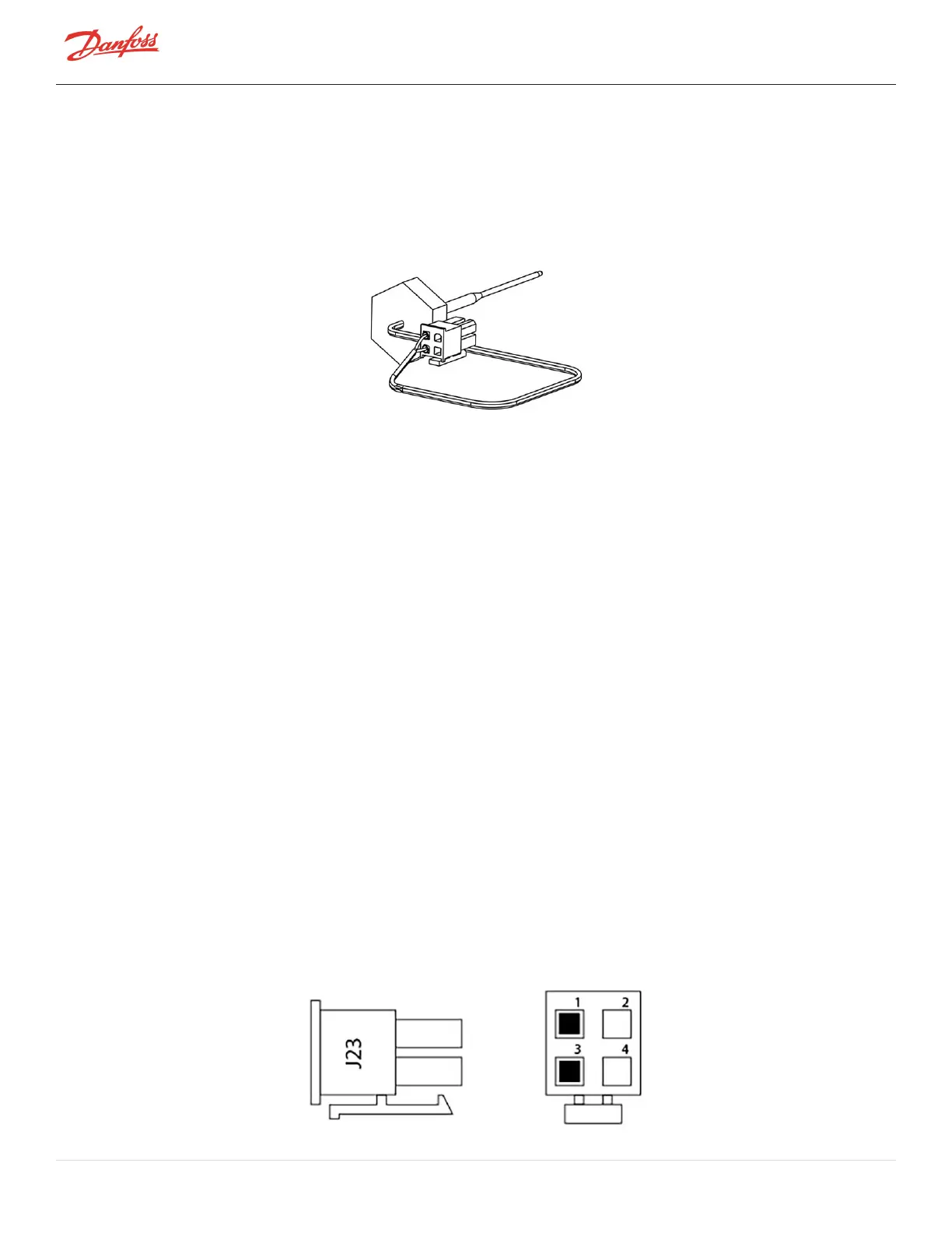
6. MeasuretheresistancebetweentheCavityTemperatureSensorterminals1and3.RefertoFigure4-
268CavityTemperatureSensorTerminal.
l
TheCavityTemperatureSensorisa10KΩ@77°F(25°C)NTCthermistor.Theresistancevalueshould
correspondtothechartinFigure4-273Temperaturevs.Resistanceonpage246.
7. MeasuretheresistanceoftheCavityTemperatureSensorterminals1and3toground.
l
Theresistancevalueshouldbeopenorinfinite.
8. ConnecttheCavityTemperatureSensorCable,J23,totheBackplane.
9. InstalltheServiceSideCover.RefertoSection4.1.3.1ServiceSideCoverRemovalandInstallationon
page54.
10. Returnthecompressortonormaloperation.
Figure 4-268 Cavity Temperature Sensor Terminal
Page 242 of 294 - M-SV-001-EN Rev. H 1/23/2023