4.3 Compressor Interface Module
TheCompressorInterfaceModule(CIM),alsoreferredtoastheCompressorI/OBoard,allowstheusertocontroland
communicatewiththecompressor,andallowsthecompressortoreturnstatusandsensorinformationtotheuser.
RefertoFigure4-18CompressorInterfaceModulePorts&Jumpers.
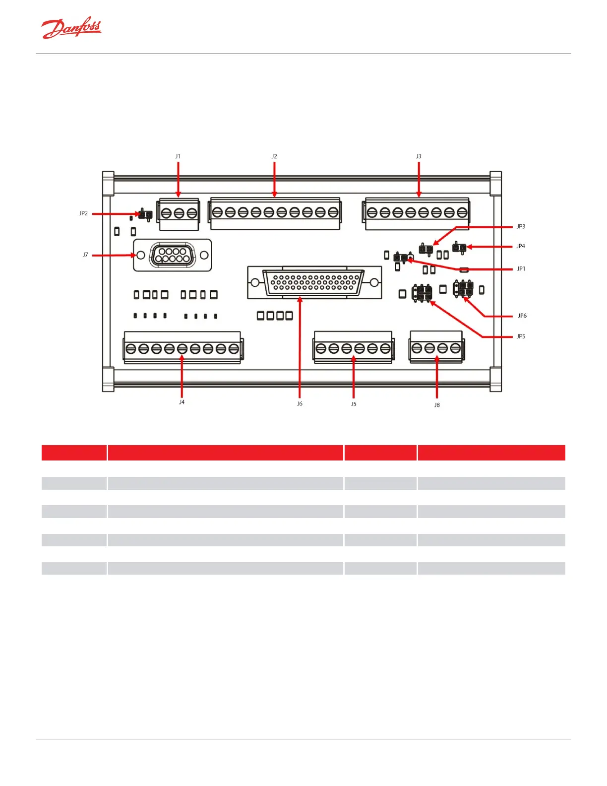
Figure 4-18 Compressor Interface Module Ports & Jumpers
Table 4-8 CIM Ports and Jumpers
No. Component No. Component
J1 RS-485CommunicationPort
JP1
AnalogOutputVoltage
J2 Input/Output JP2 MODBUSTerminator
J3 Input/Output JP3 Entry
J4 EXV1andEXV2Control JP4 Leave
J5 LiquidLevelInput JP5 LIQLEV1
J6 CompressorInterfaceCableConnection JP6 LIQLEV2
J7 RS-232ExternalCommunicationPort
J8 ExternalSensorInputs
4.3.1 Compressor Interface Module Connection Descriptions
J1 – RS-485 external communication port
l
JumperJP2requiredatendofModbusline
J2 – Input/output
l
DEMAND–Pin1&2–Analoginputtodrivecompressor(0-10V)
l
I/LOCK–Pin3&4–Interlocksafetyswitch:mustbepartofaclosedcircuittostartcompressor
Page 60 of 294 - M-SV-001-EN Rev. H 1/23/2023