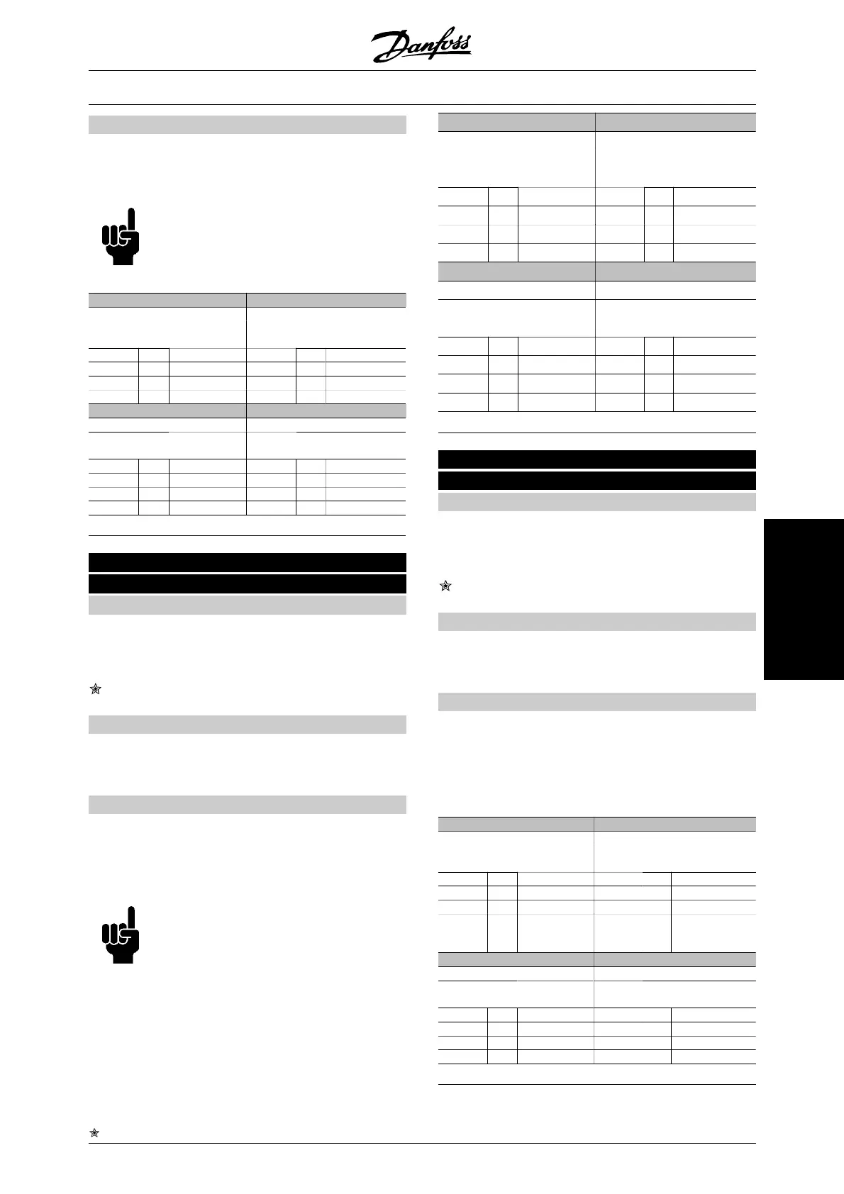
Description of choice:
The table below shows when the motor is running and
is coasting when Digital input [0], Serial communica-
tion [1], Logic and [2] or Logic or [3] has been selected.
NB!
Please note that terminal 27 and bit 03 of
the control word are active in the case of
logic '0'.
Digital input [0] Serial communication [1]
Serial Serial
Kl. 27
com
.
Function Kl. 27 com
.
Function
0 0 Coasting 0 0 Coasting
0 1 Coasting 0 1 Motor run.
1 0 Motor run. 1 0 Coasting
1 1 Motor run. 1 1 Motor run.
Logic and[2] Logic or[3]
Serial Serial
Kl. 27
com
.
Function Kl. 27 com
.
Function
0 0 Coasting 0 0 Coasting
0 1 Motor run. 0 1 Coasting
1 0 Motor run. 1 0 Coasting
1 1 Motor run. 1 1 Motor run.
504 DC brake
(DC BRAKE)
Value:
Digital input (DIGITAL INPUT) [0]
Serial communication (SERIAL PORT) [1]
Logic and (LOGIC AND) [2]
Logic or (LOGIC OR) [3]
Function:
See functional description under parameter 503
Coasting.
Description of choice:
The table below shows when the motor is running and
is DC-braking when Digital input [0], Serial communi-
cation [1], Logic and [2] or Logic or [3] has been selec-
ted.
NB!
Please note that DC braking inverse [3] via
terminal 19, terminal 27 and bit 03 of the
control word is active in the case of logic
'0'.
Digital input [0] Serial communication [1]
Serial Serial
Term.
19/27
co
m.
Function Term.
19/27
co
m.
Function
0 0 DC-brake 0 0 DC-brake
0 1 DC-brake 0 1 Motor run.
1 0 Motor run. 1 0 DC-brake
1 1 Motor run. 1 1 Motor run.
Logic and [2] Logic or [3]
Serial Serial
Term.
19/27
co
m.
Function Term.
19/27
co
m.
Function
0 0 DC-brake 0 0 DC-brake
0 1 Motor run. 0 1 DC-brake
1 0 Motor run. 1 0 DC-brake
1 1 Motor run. 1 1 Motor run.
505 Start
(START)
Value:
Digital input (DIGITAL INPUT) [0]
Serial communication (SERIAL PORT) [1]
Logic and (LOGIC AND) [2]
Logic or (LOGIC OR) [3]
Function:
See functional description under parameter 503
Coasting.
Description of choice:
The table below shows when the motor has stopped
and gives the situations in which the frequency con-
verter has a start command when Digital input [0],
Serial communication [1], Logic and [2] or Logic or [3]
has been selected.
Digital input [0] Serial communication [1]
Serial Serial
Kl.18
com
.
Function Kl.18 com
.
Function
0 0 Stop 0 0 Stop
0 1 Stop 0 1 Start
1 0 Start 1 0 Stop
1 1 Start 1 1 Start
Logic and [2] Logic or [3]
Serial Serial
Kl.18
com
.
Function Kl.18 com
.
Function
0 0 Stop 0 0 Stop
0 1 Stop 0 1 Start
1 0 Stop 1 0 Start
1 1 Start 1 1 Start
VLT
®
6000 HVAC Series
= factory setting, () = display text, [] = value for use in communication via serial communication port
MG.61.B5.02 - VLT
®
is a registered Danfoss trademark 167
Programming

 Loading...


