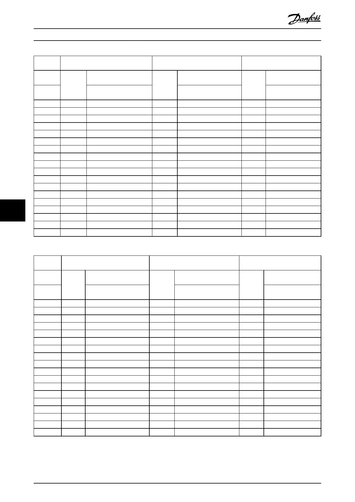
380–415 V
60 Hz
Terminals X1+X2 Terminals X3+X4 Terminals A+B
Current
rating
Ordering
number
Description
Ordering
number
Description
Ordering
number
Description
[A]
[Mains input and output
terminals]
[Capacitor disconnect
terminals]
[Thermal switch
terminals]
10 175U0258 WDU 6 600 V 50 A 175U0257 WDU 2.5 600 V 25 A 175U0257 WDU 2.5 600 V 25 A
14 175U0258 WDU 6 600 V 50 A 175U0257 WDU 2.5 600 V 25 A 175U0257 WDU 2.5 600 V 25 A
22 175U0259 WDU 10 600 V 65 A 175U0257 WDU 2.5 600 V 25 A 175U0257 WDU 2.5 600 V 25 A
29 175U0259 WDU 10 600 V 65 A 175U0257 WDU 2.5 600 V 25 A 175U0257 WDU 2.5 600 V 25 A
34 175U0260 WDU 16 600 V 85 A 175U0259 WDU 10 600 V 65 A 175U0257 WDU 2.5 600 V 25 A
40 175U0260 WDU 16 600 V 85 A 175U0259 WDU 10 600 V 65 A 175U0257 WDU 2.5 600 V 25 A
55 175U0260 WDU 16 600 V 85 A 175U0259 WDU 10 600 V 65 A 175U0257 WDU 2.5 600 V 25 A
66 175U0261 WDU 35 1000 V 150 A 175U0260 WDU 16 600 V 85 A 175U0257 WDU 2.5 600 V 25 A
82 175U0261 WDU 35 1000 V 150 A 175U0260 WDU 16 600 V 85 A 175U0257 WDU 2.5 600 V 25 A
96 175U0262 WDU 50N 600 V 150 A 175U0260 WDU 16 600 V 85 A 175U0257 WDU 2.5 600 V 25 A
133 175U0262 WDU 50N 600 V 150 A 175U0260 WDU 16 600 V 85 A 175U0257 WDU 2.5 600 V 25 A
171 175U0263 WFF70N/AH 1000 V 183 A 175U0261 WDU 35 1000 V 150 A 175U0257 WDU 2.5 600 V 25 A
204 175U0263 WFF70N/AH 1000 V 183 A 175U0261 WDU 35 1000 V 150 A 175U0257 WDU 2.5 600 V 25 A
251 175U0265 WFF300/AH 1000 V 500 A 175U0264 WDU 95N 1000 V 228 A 175U0257 WDU 2.5 600 V 25 A
304 175U0265 WFF300/AH 1000 V 500 A 175U0264 WDU 95N 1000 V 228 A 175U0257 WDU 2.5 600 V 25 A
325 175U0265 WFF300/AH 1000 V 500 A 175U0264 WDU 95N 1000 V 228 A 175U0257 WDU 2.5 600 V 25 A
381 175U0265 WFF300/AH 1000 V 500 A 175U0264 WDU 95N 1000 V 228 A 175U0257 WDU 2.5 600 V 25 A
480 175U0265 WFF300/AH 1000 V 500 A 175U0264 WDU 95N 1000 V 228 A 175U0257 WDU 2.5 600 V 25 A
Table 8.7 Terminal Kits, 380–415 V 60 Hz
440–480 V
60 Hz
Terminals X1+X2 Terminals X3+X4 Terminals A+B
Current
rating
Ordering
number
Description
Ordering
number
Description
Ordering
number
Description
[A]
[Mains input and output
terminals]
[Capacitor disconnect
terminals]
[Thermal switch
terminals]
10 175U0258 WDU 6 600 V 50 A 175U0257 WDU 2.5 600 V 25 A 175U0257 WDU 2.5 600 V 25 A
14 175U0258 WDU 6 600 V 50 A 175U0257 WDU 2.5 600 V 25 A 175U0257 WDU 2.5 600 V 25 A
19 175U0259 WDU 10 600 V 65 A 175U0257 WDU 2.5 600 V 25 A 175U0257 WDU 2.5 600 V 25 A
25 175U0259 WDU 10 600 V 65 A 175U0257 WDU 2.5 600 V 25 A 175U0257 WDU 2.5 600 V 25 A
31 175U0260 WDU 16 600 V 85 A 175U0259 WDU 10 600 V 65 A 175U0257 WDU 2.5 600 V 25 A
36 175U0260 WDU 16 600 V 85 A 175U0259 WDU 10 600 V 65 A 175U0257 WDU 2.5 600 V 25 A
48 175U0260 WDU 16 600 V 85 A 175U0259 WDU 10 600 V 65 A 175U0257 WDU 2.5 600 V 25 A
60 175U0261 WDU 35 1000 V 150 A 175U0260 WDU 16 600 V 85 A 175U0257 WDU 2.5 600 V 25 A
73 175U0261 WDU 35 1000 V 150 A 175U0260 WDU 16 600 V 85 A 175U0257 WDU 2.5 600 V 25 A
95 175U0262 WDU 50N 600 V 150 A 175U0260 WDU 16 600 V 85 A 175U0257 WDU 2.5 600 V 25 A
118 175U0262 WDU 50N 600 V 150 A 175U0260 WDU 16 600 V 85 A 175U0257 WDU 2.5 600 V 25 A
154 175U0263 WFF70N/AH 1000 V 183 A 175U0261 WDU 35 1000 V 150 A 175U0257 WDU 2.5 600 V 25 A
183 175U0263 WFF70N/AH 1000 V 183 A 175U0261 WDU 35 1000 V 150 A 175U0257 WDU 2.5 600 V 25 A
231 175U0265 WFF300/AH 1000 V 500 A 175U0264 WDU 95N 1000 V 228 A 175U0257 WDU 2.5 600 V 25 A
291 175U0265 WFF300/AH 1000 V 500 A 175U0264 WDU 95N 1000 V 228 A 175U0257 WDU 2.5 600 V 25 A
355 175U0265 WFF300/AH 1000 V 500 A 175U0264 WDU 95N 1000 V 228 A 175U0257 WDU 2.5 600 V 25 A
380 175U0265 WFF300/AH 1000 V 500 A 175U0264 WDU 95N 1000 V 228 A 175U0257 WDU 2.5 600 V 25 A
436 175U0265 WFF300/AH 1000 V 500 A 175U0264 WDU 95N 1000 V 228 A 175U0257 WDU 2.5 600 V 25 A
Table 8.8 Terminal Kits, 440–480 V 60 Hz
Spare Parts
VLT
®
Advanced Harmonic Filter AHF 005/AHF 010
138 Danfoss A/S © 10/2016 All rights reserved. MG80C502
88
 Loading...


