9.4 Mounting Congurations
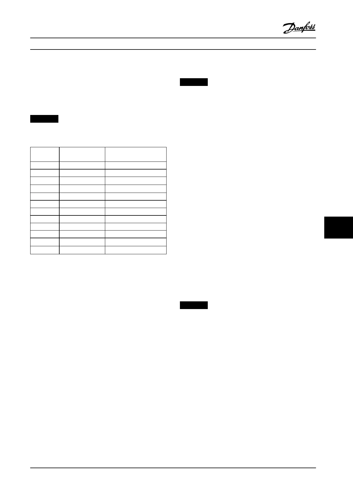
Table 9.1 lists the available mounting congurations for
each enclosure. For specic wall mount or pedestal mount
installation instructions, see the operating guide. See also
chapter 8 Exterior and Terminal Dimensions.
NOTICE!
Improper mounting can result in overheating and
reduced performance.
Enclosure Wall/cabinet mount Pedestal mount
(Standalone)
D1h X X
D2h X X
D3h
X
1)
–
D4h
X
1)
–
D5h – X
D6h – X
D7h – X
D8h – X
E1h – X
E2h – X
E3h
X
1)
–
E4h
X
1)
–
Table 9.1 Mounting Congurations
1) Can be wall mounted, but Danfoss recommends that the drive is
panel mounted inside an enclosure due to its protection rating.
2) Drive can be mounted in the following congurations:
- Vertically on the backplate of the panel.
- Vertically upside down on the backplate of the panel.
Contact factory.
- Horizontally on its back, mounted on the backplate of the
panel. Contact factory.
- Horizontally on its side, mounted on oor of the panel.
Contact factory.
Mounting considerations:
•
Locate the unit as near to the motor as possible.
See for the maximum motor cable length.
•
Ensure unit stability by mounting the unit to a
solid surface.
•
Ensure that the strength of the mounting location
supports the unit weight.
•
Ensure that there is enough space around the
unit for proper cooling. Refer to
chapter 5.13 Back-channel Cooling Overview.
•
Ensure enough access to open the door.
•
Ensure cable entry from the bottom.
9.5
Cooling
NOTICE!
Improper mounting can result in overheating and
reduced performance. For proper mounting, refer to
chapter 9.4 Mounting Congurations.
•
Ensure that top and bottom clearance for air
cooling is provided. Clearance requirement:
225 mm (9 in).
•
Provide sucient airow ow rate. See Table 9.2.
•
Consider derating for temperatures starting
between 45 °C (113 °F) and 50 °C (122 °F) and
elevation 1000 m (3300 ft) above sea level. See
chapter 9.6 Derating for detailed information on
derating.
The drive utilizes a back-channel cooling concept that
removes heat sink cooling air. The heat sink cooling air
carries approximately 90% of the heat out of the back
channel of the drive. Redirect the back-channel air from
the panel or room by using:
•
Duct cooling
Back-channel cooling kits are available to direct
the heat sink cooling air out of the panel when
IP20/Chassis drives are installed in Rittal
enclosures. Use of these kits reduce the heat in
the panel and smaller door fans can be specied.
•
Back-wall cooling
Installing top and base covers to the unit allows
the back-channel cooling air to be ventilated out
of the room.
NOTICE!
For E3h and E4h enclosures (IP20/Chassis), at least 1
door fan is required on the enclosure to remove the heat
not contained in the back-channel of the drive. It also
removes any additional losses generated by other
components inside the drive. To select the appropriate
fan size, calculate the total required airow.
Secure the necessary airow over the heat sink.
Mechanical Installation Con... Design Guide
MG22B222 Danfoss A/S © 01/2018 All rights reserved. 151
9 9

 Loading...


