10.6.3 Motor Insulation
For motor cable lengths that are less than or equal to the
maximum cable length listed in chapter 7.6 Cable Speci-
cations, use the motor insulation ratings shown in
Table 10.18. If a motor has lower insulation rating, Danfoss
recommends using a dU/dt or sine-wave lter.
Nominal mains voltage Motor insulation
U
N
≤420 V
Standard U
LL
=1300 V
420 V<U
N
≤ 500 V Reinforced U
LL
=1600 V
500 V<U
N
≤ 600 V Reinforced U
LL
=1800 V
600 V<U
N
≤ 690 V Reinforced U
LL
=2000 V
Table 10.18 Motor Insulation Ratings
10.6.4 Motor Bearing Currents
To eliminate circulating bearing currents in all motors
installed with the drive, install NDE (non-drive end)
insulated bearings. To minimize DE (drive end) bearing and
shaft currents, ensure proper grounding of the drive,
motor, driven machine, and motor to the driven machine.
Standard mitigation strategies:
•
Use an insulated bearing.
•
Follow proper installation procedures.
- Ensure that the motor and load motor
are aligned.
- Follow the EMC Installation guideline.
- Reinforce the PE so the high frequency
impedance is lower in the PE than the
input power leads.
- Provide a good high frequency
connection between the motor and the
drive. Use a shielded cable that has a
360° connection in the motor and the
drive.
- Ensure that the impedance from the
drive to building ground is lower than
the grounding impedance of the
machine. This procedure can be dicult
for pumps.
- Make a direct ground connection
between the motor and load motor.
•
Lower the IGBT switching frequency.
•
Modify the inverter waveform, 60° AVM vs.
SFAVM.
•
Install a shaft grounding system or use an
isolating coupling.
•
Apply conductive lubrication.
•
Use minimum speed settings if possible.
•
Try to ensure that the mains voltage is balanced
to ground. This procedure can be dicult for IT,
TT, TN-CS, or grounded leg systems.
•
Use a dU/dt or sine-wave lter.
10.7 Braking
10.7.1 Brake Resistor Selection
In certain applications, such as a tunnel or underground
railway station ventilation system, it is desirable to bring
the motor to a stop more rapidly than can be achieved
through controlling via ramp down or by free wheeling. In
such applications, typically a dynamic brake with a brake
resistor is used. Using a brake resistor ensures that the
energy is absorbed in the resistor and not in the drive. For
more information, see the VLT
®
Brake Resistor MCE 101
Design Guide.
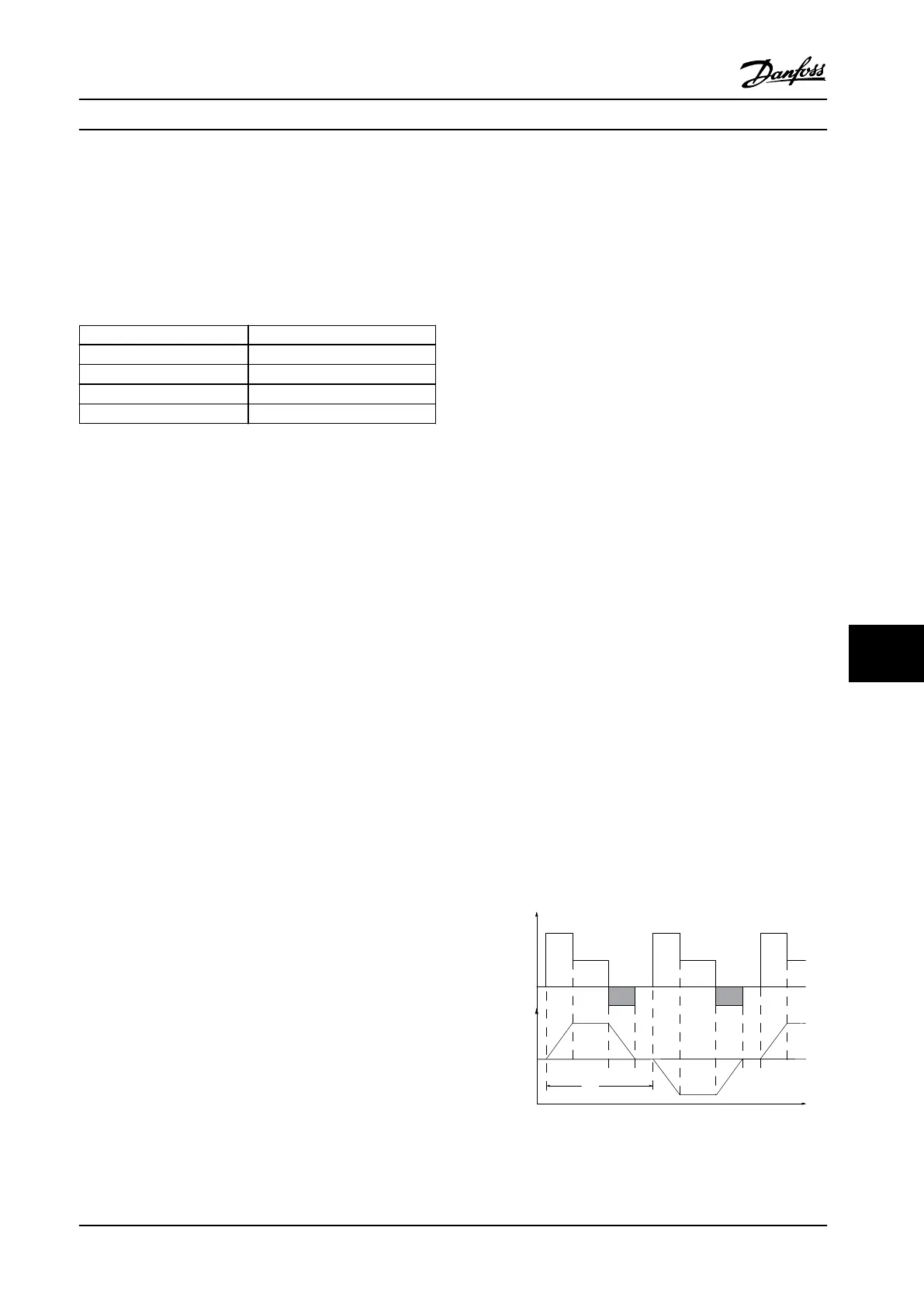
If the amount of kinetic energy transferred to the resistor
in each braking period is not known, the average power
can be calculated based on the cycle time and braking
time (intermittent duty cycle). The resistor intermittent
duty cycle indicates the duty cycle at which the resistor is
active. Figure 10.11 shows a typical braking cycle.
Motor suppliers often use S5 when stating the allowed
load, which is an expression of intermittent duty cycle. The
intermittent duty cycle for the resistor is calculated as
follows:
Duty cycle=t
b
/T
T=cycle time in s
t
b
is the braking time in s (of the cycle time)
T
ta
tc
tb
to ta
tc
tb
to ta
130BA167.10
Charge
Temps
Vitesse
Figure 10.11 Typical Braking Cycle
Electrical Installation Con... Design Guide
MG22B222 Danfoss A/S © 01/2018 All rights reserved. 167
10 10

 Loading...


