5.9 Advanced Minimum Speed Monitoring
Overview
Some pumps are sensitive to operating at low speed.
Insucient cooling or lubrication at low speed are typical
reasons.
Under overload conditions, the drive protects itself using
its integral protection features, which include lowering the
speed. For example, the current limit controller can lower
the speed. Sometimes, the speed can go lower than the
speed specied in parameter 4-11 Motor Speed Low Limit
[RPM] and parameter 4-12 Motor Speed Low Limit [Hz].
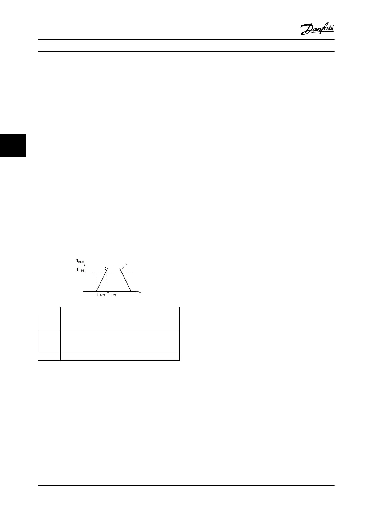
If the speed drops below a certain value, the advanced
minimum-speed monitoring feature trips the drive. If the
pump motor does not reach the speed specied in
parameter 1-86 Trip Speed Low [RPM] within the time
specied in parameter 1-79 Pump Start Max Time to Trip
(ramping up takes too long), the drive trips. Timers for
parameter 1-71 Start Delay and parameter 1-79 Pump Start
Max Time to Trip start at the same time when the start
command is issued. For example, if the value in
parameter 1-71 Start Delay is more than or equal to the
value in parameter 1-79 Pump Start Max Time to Trip, the
drive never starts.
T
1-71
Parameter 1-71 Start Delay.
T
1-79
Parameter 1-79 Pump Start Max Time to Trip. This time
includes the time in T
1-71
.
N
1-86
Parameter 1-86 Trip Speed Low [RPM]. If the speed
drops below this value during normal operation, the
drive trips.
1 Normal operation.
Figure 5.15 Advanced Minimum Speed Monitoring
5.10 Dynamic Braking Overview
Dynamic braking slows the motor using 1 of the following
methods:
•
AC brake
The brake energy is distributed in the motor by
changing the loss conditions in the motor
(parameter 2-10 Brake Function = [2]). The AC
brake function cannot be used in applications
with high cycling frequency since this situation
overheats the motor.
•
DC brake
An overmodulated DC current added to the AC
current works as an eddy current brake
(parameter 2-02 DC Braking Time ≠ 0 s).
•
Resistor brake
A brake IGBT keeps the overvoltage under a
certain threshold by directing the brake energy
from the motor to the connected brake resistor
(parameter 2-10 Brake Function = [1]). For more
information on selecting a brake resistor, see VLT
®
Brake Resistor MCE 101 Design Guide.
For drives equipped with the brake option, a brake IGBT
along with terminals 81(R-) and 82(R+) are included for
connecting an external brake resistor.
The function of the brake IGBT is to limit the voltage in the
DC link whenever the maximum voltage limit is exceeded.
It limits the voltage by switching the externally mounted
resistor across the DC bus to remove excess DC voltage
present on the bus capacitors.
External brake resistor placement has the advantages of
selecting the resistor based on application need,
dissipating the energy outside of the control panel, and
protecting the drive from overheating if the brake resistor
is overloaded.
The brake IGBT gate signal originates on the control card
and is delivered to the brake IGBT via the power card and
gatedrive card. Also, the power and control cards monitor
the brake IGBT for a short circuit. The power card also
monitors the brake resistor for overloads.
Product Features
VLT
®
AQUA Drive FC 202
32 Danfoss A/S © 01/2018 All rights reserved. MG22B222
55

 Loading...


