If a derag is triggered from a drive-stopped state, the rst
o delay is skipped. The deragging event consists of
several cycles. One cycle consisting of 1 pulse in the
reverse direction followed by 1 pulse in the forward
direction. Deragging is considered nished after the
specied number of cycles have completed. More specif-
ically, on the last pulse (it is always forward) of the last
cycle, the derag is considered nished after the deragging
run-time expires (the drive is running at derag speed). In
between pulses, the drive output coasts for a specied o-
delay time to let debris in the pump settle.
NOTICE!
Do not enable deragging if the pump cannot operate in
reverse direction.
There are 3 dierent notications for an ongoing
deragging event:
•
Status in the LCP: Auto Remote Derag.
•
A bit in the extended status word
(bit 23, 80 0000 hex).
•
A digital output can be congured to reect the
active deragging status.
Depending on the application and the purpose of using it,
this feature can be used as a preventive or reactive
measure and can be triggered/started in the following
ways:
•
On each start command (parameter 29-11 Derag
at Start/Stop).
•
On each stop command (parameter 29-11 Derag
at Start/Stop).
•
On each start/stop command
(parameter 29-11 Derag at Start/Stop).
•
On digital input (parameter group 5-1* Digital
Inputs).
•
On drive action with the smart logic controller
(parameter 13-52 SL Controller Action).
•
As timed action (parameter group 23-** Time-
based Functions).
•
On high power (parameter group 29-2* Derag
Power Tuning).
5.7
Pre/post Lube Overview
Certain motors require lubrication of their mechanical parts
before and during running to prevent damage/wear. This
situation is especially the case when the motor has not
been running for extended periods of time. Pre-lube also
supports applications that require certain exhaust fans to
be running. The pre-lube feature signals an external device
to start performing a specic action for a user-dened
time, beginning at the rising edge of a run command (for
example, start request). Furthermore, a start delay
(parameter 1-71 Start Delay) can be entered such that the
pre-lube occurs only while the drive is stopped and the
pre-lube completes just before the drive starts to ramp up.
Pre-lube can also be congured such that the external
device remains signaled always when the drive is in a
running state, or such that the signal stays on after the
motor has stopped (parameter 29-42 Post Lube Time).
Application examples include a device to lubricate the
mechanical parts of a motor/pump or some type of
exhaust fan unit.
An example use case for a lubrication device would be to
start lubrication at the rising edge of a start request. Delay
the start for a time and stop lubrication when the delay
expires and the drive starts.
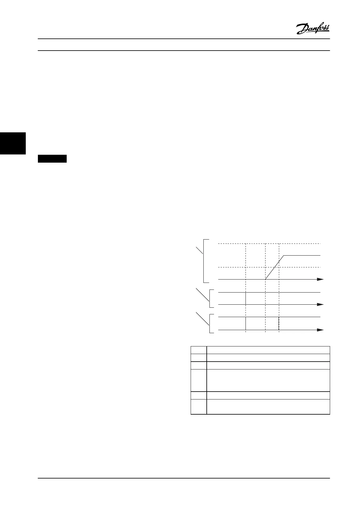
Figure 5.13 shows a
dierent usage of the feature. In this
case, the delay expires while the drive is already ramping
up. See the related parameters in Table 5.1.
130BD765.10
N
MAX
N
MIN
0
1
1
0
0
1
2
3
t1 t3t2
T
T
T
1 Speed curve.
2 Start command (for example, terminal 18).
3 Pre-lube output signal.
t
1
Start command issued (for example, terminal 18 is set
active). The start delay timer (parameter 1-71 Start Delay)
and the pre-lube timer (parameter 29-41 Pre Lube Time).
t
2
The start delay timer expires. The drive starts to ramp up.
t
3
The pre-lube timer (parameter 29-41 Pre Lube Time)
expires.
Figure 5.13 Pre/post Lube Function Example
Product Features
VLT
®
AQUA Drive FC 202
30 Danfoss A/S © 01/2018 All rights reserved. MG22B222
55

 Loading...


