11 Basic Operating Principles of a Drive
This chapter provides an overview of the primary
assemblies and circuitry of a Danfoss drive. It describes the
internal electrical and signal processing functions. A
description of the internal control structure is also
included.
11.1 Description of Operation
A drive is an electronic controller that supplies a regulated
amount of AC power to a 3-phase inductive motor. By
supplying variable frequency and voltage to the motor, the
drive varies the motor speed or maintains a constant
speed as the load on the motor changes. Also, the drive
can stop and start a motor without the mechanical stress
associated with a line start.
In its basic form, the drive can be divided into the
following 4 main areas:
Rectier
The rectier consists of SCRs or diodes that convert 3-
phase AC voltage to pulsating DC voltage.
DC link (DC bus)
The DC link consists of inductors and capacitor banks that
stabilize the pulsating DC voltage.
Inverter
The inverter uses IGBTs to convert the DC voltage to
variable voltage and variable frequency AC.
Control
The control area consists of software that runs the
hardware to produce the variable voltage that controls and
regulates the AC motor.
L1
L2
L3
T1
T2
T3
1 2 3
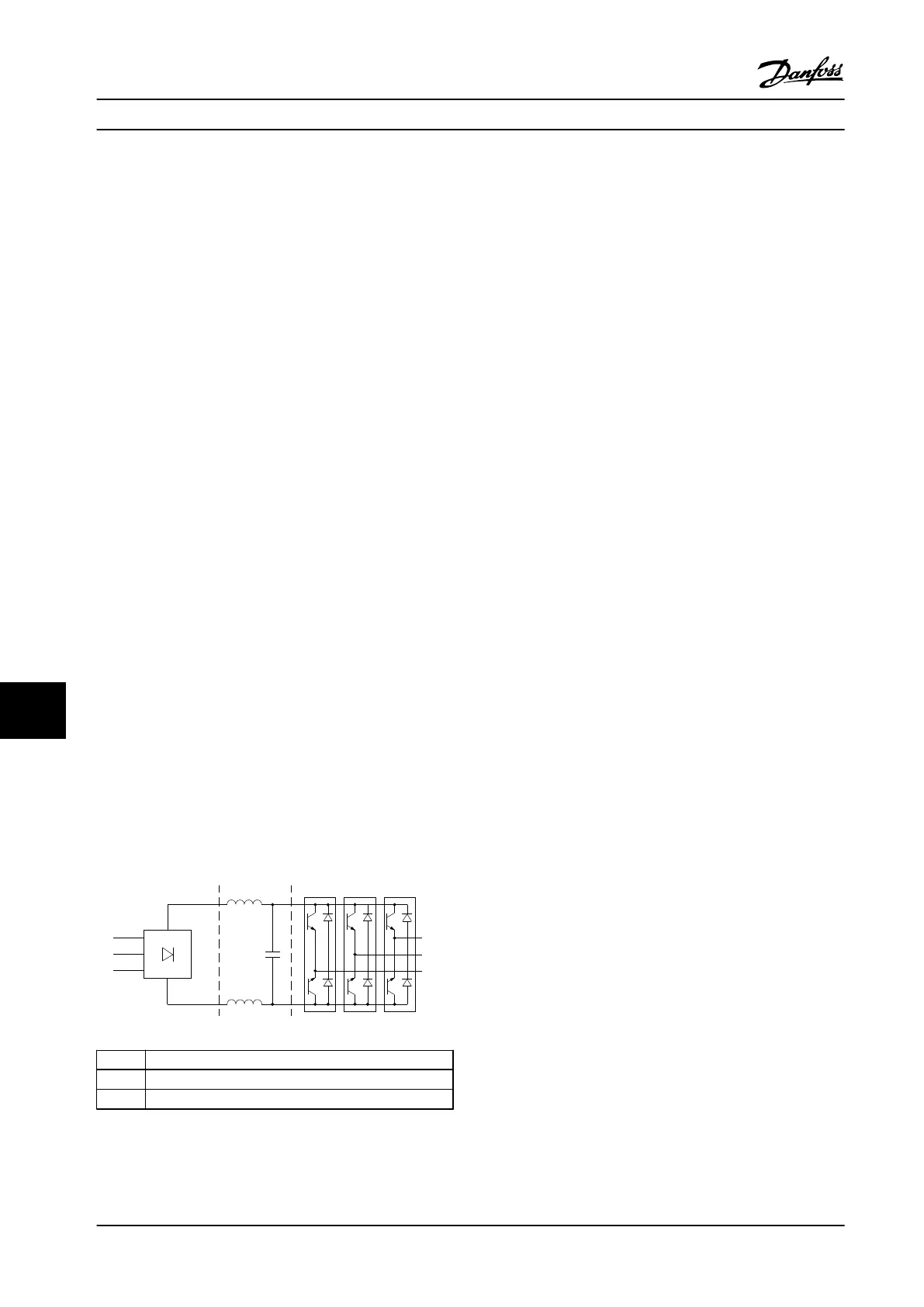
130BF777.10
1 Rectier (SCR/diodes)
2 DC link (DC bus)
3 Inverter (IGBTs)
Figure 11.1 Internal Processing
11.2 Drive Controls
The following processes are used to control and regulate
the motor:
•
User input/reference.
•
Feedback handling.
•
User-dened control structure.
- Open loop/closed-loop mode.
- Motor control (speed, torque, or
process).
•
Control algorithms (VVC
+
, ux sensorless, ux
with motor feedback, and internal current control
VVC
+
).
11.2.1 User Inputs/References
The drive uses an input source (also called reference) to
control and regulate the motor. The drive receives this
input either:
•
Manually via the LCP. This method is referred to
as local (Hand On).
•
Remotely via analog/digital inputs and various
serial interfaces (RS485, USB, or an optional
eldbus). This method is referred to as remote
(Auto On) and is the default input setting.
Active reference
The term active reference refers to the active input source.
The active reference is congured in
parameter 3-13 Reference Site. See Figure 11.2 and
Table 11.1.
For more information, see the programming guide.
Basic Operating Principles ...
VLT
®
AQUA Drive FC 202
188 Danfoss A/S © 01/2018 All rights reserved. MG22B222
1111

 Loading...


