12.9 Wiring Conguration for a Relay Set-up
with Smart Logic Control
Parameters
FC
+24 V
+24 V
D IN
D IN
D IN
COM
D IN
D IN
D IN
D IN
+10 V
A IN
A IN
COM
A OUT
COM
R1R2
12
13
18
19
20
27
29
32
33
37
50
53
54
55
42
39
01
02
03
04
05
06
130BB839.10
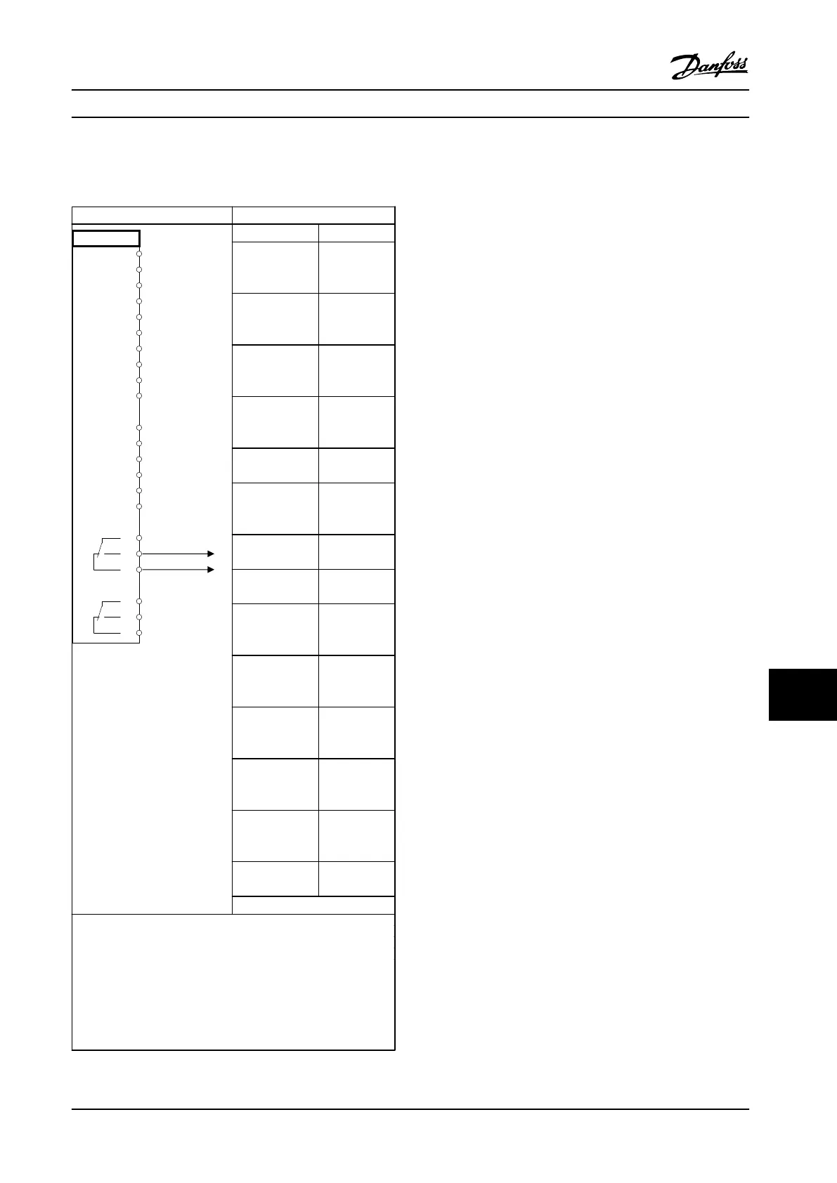
Function Setting
Parameter 4-30
Motor Feedback
Loss Function
[1] Warning
Parameter 4-31
Motor Feedback
Speed Error
100 RPM
Parameter 4-32
Motor Feedback
Loss Timeout
5 s
Parameter 7-00 S
peed PID
Feedback Source
[2] MCB 102
Parameter 17-11
Resolution (PPR)
1024*
Parameter 13-00
SL Controller
Mode
[1] On
Parameter 13-01
Start Event
[19] Warning
Parameter 13-02
Stop Event
[44] Reset key
Parameter 13-10
Comparator
Operand
[21] Warning
no.
Parameter 13-11
Comparator
Operator
[1] ≈ (equal)*
Parameter 13-12
Comparator
Value
90
Parameter 13-51
SL Controller
Event
[22]
Comparator 0
Parameter 13-52
SL Controller
Action
[32] Set digital
out A low
Parameter 5-40 F
unction Relay
[80] SL digital
output A
*=Default value
Notes/comments:
If the limit in the feedback monitor is exceeded, warning 90,
Feedback Mon. is issued. The SLC monitors warning 90, Feedback
Mon. and if the warning becomes true, relay 1 is triggered.
External equipment may require service. If the feedback error
goes below the limit again within 5 s, the drive continues and
the warning disappears. Reset relay 1 by pressing [Reset] on the
LCP.
Table 12.13 Wiring Conguration for a Relay Set-up with
Smart Logic Control
12.10 Wiring Conguration for a
Submersible Pump
The system consists of a submersible pump controlled by a
Danfoss VLT
®
AQUA Drive and a pressure transmitter. The
transmitter gives a 4–20 mA feedback signal to the drive,
which keeps a constant pressure by controlling the speed
of the pump. To design a drive for a submersible pump
application, there are a few important issues to consider.
Select the drive according to motor current.
•
The CAN motor is a motor with a stainless steel
can between the rotor and stator that contains a
larger and a more magnetic resistant air-gap than
on a normal motor. This weaker
eld results in
the motors being designed with a higher rated
current than a normal motor with similar rated
power.
•
The pump contains thrust bearings that are
damaged when running below minimum speed,
which is normally 30 Hz.
•
The motor reactance is nonlinear in submersible
pump motors and, therefore, automatic motor
adaption (AMA) may not be possible. Normally,
submersible pumps are operated with long motor
cables that might eliminate the nonlinear motor
reactance and enable the drive to perform AMA.
If AMA fails, the motor data can be set from
parameter group 1-3* Adv. Motor Data (see the
motor datasheet). If AMA has succeeded, the
drive compensates for the voltage drop in the
long motor cables. If the advanced motor data
are set manually, the length of the motor cable
must be considered to optimize system
performance.
•
It is important that the system is operated with a
minimum of wear and tear on the pump and
motor. A Danfoss sine-wave lter can lower the
motor insulation stress and increase lifetime
(check actual motor insulation and the drive
dU/dt
specication). Most manufacturers of
submersible pumps require the use of output
lters.
•
EMC performance can be dicult to achieve
because the special pump cable, which is able to
withstand the wet conditions in the well, is
normally unshielded. A solution could be to use a
shielded cable above the well and attach the
shield to the well pipe, if it is made of steel. A
sine-wave lter also reduces the EMI from
unshielded motor cables.
Application Examples Design Guide
MG22B222 Danfoss A/S © 01/2018 All rights reserved. 203
12 12

 Loading...


