The special CAN motor is used because of the wet instal-
lation conditions. Design the system according to output
current to be able to run the motor at nominal power.
To prevent damage to the thrust bearings of the pump,
and to ensure sucient motor cooling as quickly as
possible, it is important to ramp the pump from stop to
minimum speed as quick as possible. Most submersible
pump manufacturers recommend that the pump ramps to
minimum speed (30 Hz) in maximum 2–3 s. The VLT
®
AQUA Drive FC 202 is designed with initial and nal ramp
for these applications. The initial and nal ramps are 2
individual ramps, where initial ramp, if enabled, ramps the
motor from stop to minimum speed and automatically
switches to normal ramp, when minimum speed is
reached. Final ramp does the opposite from minimum
speed to stop in a stop situation. Consider also enabling
advanced minimum speed monitoring as described in
chapter 5.9 Advanced Minimum Speed Monitoring Overview.
To achieve extra pump protection, use the dry-run
detection function. For more information, see the
programming guide.
Pipe-ll mode can be enabled to prevent water
hammering. The Danfoss drive can ll the vertical pipes
using the PID controller to ramp up the pressure slowly
with a user-specied rate (units/second). If enabled, the
drive enters pipe-ll mode when it reaches minimum
speed after start-up. The pressure is slowly ramped up until
it reaches a user-specied lled setpoint, where the drive
automatically disables pipe ll mode and continues in
normal closed-loop operation.
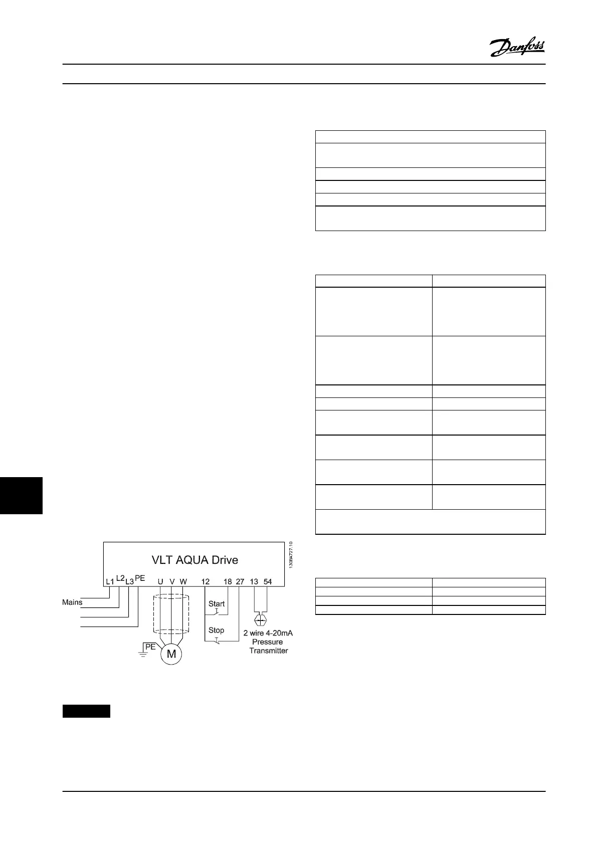
Electrical Wiring
Figure 12.4 Wiring for Submersible Pump Application
NOTICE!
Set the analog input 2, (terminal 54) format to mA.
(switch 202).
Parameter settings
Parameter
Parameter 1-20 Motor Power [kW]/parameter 1-21 Motor Power
[HP]
Parameter 1-22 Motor Voltage
Parameter 1-24 Motor Current
Parameter 1-28 Motor Rotation Check
Ensure that parameter 1-29 Automatic Motor Adaptation (AMA) is
set to [2] Enable Reduced AMA.
Table 12.14 Relevant Parameters for Submersible Pump
Application
Parameter Setting
Parameter 3-02 Minimum
Reference
The minimum reference unit
matches the unit in
parameter 20-12 Reference/
Feedback Unit
Parameter 3-03 Maximum
Reference
The maximum reference unit
matches the unit in
parameter 20-12 Reference/
Feedback Unit
Parameter 3-84 Initial Ramp Time (2 s)
Parameter 3-88 Final Ramp Time (2 s)
Parameter 3-41 Ramp 1 Ramp Up
Time
(8 s depending on size)
Parameter 3-42 Ramp 1 Ramp
Down Time
(8 s depending on size)
Parameter 4-11 Motor Speed Low
Limit [RPM]
(30 Hz)
Parameter 4-13 Motor Speed High
Limit [RPM]
(50/60 Hz)
Use the Closed-loop wizard under Quick Menu
⇒
Function Set-up, to
set up the feedback settings in the PID controller.
Table 12.15 Example of Settings for Submersible Pump
Application
Parameter
Setting
Parameter 29-00 Pipe Fill Enable Disabled
Parameter 29-04 Pipe Fill Rate (Feedback units)
Parameter 29-05 Filled Setpoint (Feedback units)
Table 12.16 Example of Settings for Pipe-Fill Mode
Application Examples
VLT
®
AQUA Drive FC 202
204 Danfoss A/S © 01/2018 All rights reserved. MG22B222
1212

 Loading...


