12.12 Wiring Conguration for a Fixed
Variable Speed Pump
L1/L2/L3 L1/L2/L3 L1/L2/L3
Power Section
RELAY 1
RELAY 2
130BA376.10
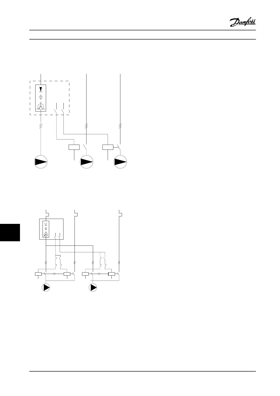
Figure 12.7 Fixed Variable Speed Pump Wiring Diagram
12.13 Wiring Conguration for Lead Pump
Alternation
130BA377.13
L1/L2/L3
FC
L1/L2/L3
L1/L2/L3
k3
k2
k3
k1
K2
K1
K1
K1
K4
K3
K4
K3
R1
R2
Figure 12.8 Lead Pump Alternation Wiring Diagram.
Every pump must be connected to 2 contactors (K1/K2 and
K3/K4) with a mechanical interlock. Thermal relays or other
motor overload protection devices must be applied
according to local regulation and/or individual demands.
•
Relay 1 (R1) and relay 2 (R2) are the built-in relays
in the drive.
•
When all relays are de-energized, the 1
st
built-in
relay that is energized cuts in the contactor
corresponding to the pump controlled by the
relay. For example, relay 1 cuts in contactor K1,
which becomes the lead pump.
•
K1 blocks for K2 via the mechanical interlock,
preventing mains from being connected to the
output of the drive (via K1).
•
Auxiliary break contact on K1 prevents K3 from
cutting in.
•
Relay 2 controls contactor K4 for on/o control of
the xed-speed pump.
•
At alternation, both relays de-energize and now
relay 2 is energized as the 1
st
relay.
For a detailed description of commissioning for mixed
pump and master/slave applications, refer to VLT
®
Cascade
Controller Options MCO 101/102 Operating Instructions.
Application Examples
VLT
®
AQUA Drive FC 202
206 Danfoss A/S © 01/2018 All rights reserved. MG22B222
1212

 Loading...


