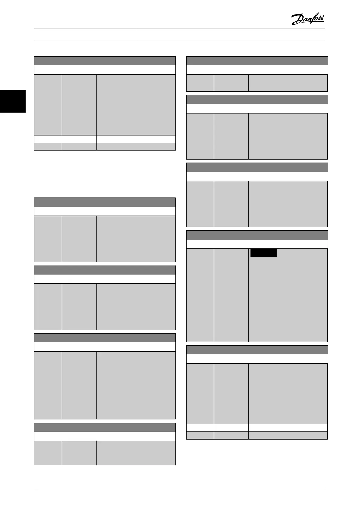
6-17 Terminal 53 Live Zero
Option: Function:
Disables the live zero monitoring,
for example if the analog outputs
are used as part of a decentral I/O
system (that is if these are used to
feed a building management
system with data, and not as part
of any control functions related to
the frequency converter).
[0] Disabled
[1] * Enabled
3.8.3 6-2* Analog Input 2
Parameters for conguring the scaling and limits for analog
input 2 (terminal 54).
6-20 Terminal 54 Low Voltage
Range: Function:
0.07 V* [ 0 - par. 6-21
V]
Enter the low voltage value. This
analog input scaling value should
correspond to the low reference
feedback value set in
parameter 6-24 Terminal 54 Low Ref./
Feedb. Value.
6-21 Terminal 54 High Voltage
Range: Function:
10 V* [ par. 6-20 -
10 V]
Enter the high voltage value. This
analog input scaling value should
correspond to the high reference
feedback value set in
parameter 6-25 Terminal 54 High
Ref./Feedb. Value.
6-22 Terminal 54 Low Current
Range: Function:
4 mA* [ 0 - par. 6-23
mA]
Enter the low current value. This
reference signal should correspond
to the low reference feedback value
set in parameter 6-24 Terminal 54
Low Ref./Feedb. Value. Set the value
at >2 mA to activate the live zero
timeout function in
parameter 6-01 Live Zero Timeout
Function.
6-23 Terminal 54 High Current
Range: Function:
20 mA* [ par. 6-22 -
20 mA]
Enter the high current value
corresponding to the high reference
feedback value set in
6-23 Terminal 54 High Current
Range: Function:
parameter 6-25 Terminal 54 High
Ref./Feedb. Value.
6-24 Terminal 54 Low Ref./Feedb. Value
Range: Function:
0* [-999999.999
- 999999.999 ]
Enter the analog input scaling value
that corresponds to the low
voltage/low current value set in
parameter 6-20 Terminal 54 Low
Voltage and parameter 6-22 Terminal
54 Low Current.
6-25 Terminal 54 High Ref./Feedb. Value
Range: Function:
100* [-999999.999
- 999999.999 ]
Enter the analog input scaling value
that corresponds to the high
voltage/high current value set in
parameter 6-21 Terminal 54 High
Voltage and parameter 6-23 Terminal
54 High Current.
6-26 Terminal 54 Filter Time Constant
Range: Function:
0.005 s* [0.005 - 10 s]
NOTICE
This parameter cannot be
adjusted while the motor is
running.
Enter the lter time constant. This is
a rst-order digital low-pass lter
time constant for suppressing
electrical noise in terminal 54.
Increasing the value improves
dampening but also increases the
time delay through the lter.
6-27 Terminal 54 Live Zero
Option: Function:
Disables the live zero-monitoring,
for example if the analog outputs
are used as part of a decentral I/O
system (that is if these are used to
feed a building management
system with data, and not as part
of any control functions related to
the frequency converter).
[0] Disabled
[1] * Enabled
Parameter Descriptions
VLT
®
HVAC Drive FC 102
108 Danfoss A/S © 10/2019 All rights reserved. M0010001
33
 Loading...


