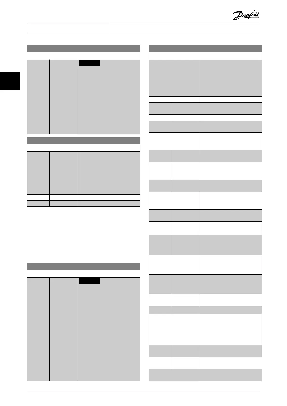
6-46 Term. X30/12 Filter Time Constant
Range: Function:
0.005 s* [0.005 - 10 s]
NOTICE
This parameter cannot be
adjusted while the motor is
running.
Enter the lter time constant. This
constant is a rst-order digital low-
pass lter time for suppressing
electrical noise in terminal X30/12.
A high value improves dampening
but also increases the delay
through the lter.
6-47 Term. X30/12 Live Zero
Option: Function:
This parameter makes it possible to
disable the live zero-monitoring. For
example, to be used if the analog
outputs are used in a decentral I/O
system (when an analog output
does not full any control function,
but feeds a data storage device).
[0] Disabled
[1] * Enabled
3.8.6 6-5* Analog Output 1
Parameters for conguring the scaling and limits for analog
output 1, that is terminal 42. Analog outputs are current
outputs: 0/4–20 mA. Common terminal (terminal 39) is the
same terminal and has the same electrical potential for
analog common and digital common connection.
Resolution on analog output is 12 bit.
6-50 Terminal 42 Output
Option: Function:
NOTICE
Values for setting the
minimum reference are found
in open loop
parameter 3-02 Minimum
Reference and for closed loop
parameter 20-13 Minimum
Reference/Feedb.. Values for
maximum reference for open
loop are found in
parameter 3-03 Maximum
Reference and for closed loop
parameter 20-14 Maximum
Reference/Feedb.
This parameter enables the function
of terminal 42 as an analog current
6-50 Terminal 42 Output
Option: Function:
output. Depending on the option
selected, the output is either 0–
20 mA or 4–20 mA. The current
value can be read out in the LCP in
parameter 16-65 Analog Output 42
[mA].
[0] No operation
[52] MCO 0-20mA/
0-10V
[53] MCO 4-20mA
[86] Pressure
Sensor 1
[87] Pressure
Sensor 1 (4-20
mA)
[88] Pressure
Sensor 2
[89] Pressure
Sensor 2 (4-20
mA)
[93] Pressure
Sensor 3
[94] Pressure
Sensor 3 (4-20
mA)
[100] Output freq.
0-100
0–100 Hz, (0–20 mA).
[101] Reference
Min-Max
Minimum reference–Maximum
reference, (0–20 mA).
[102] Feedback
+-200%
-200% to +200% of
parameter 20-14 Maximum
Reference/Feedb., (0–20 mA).
[103] Motor cur. 0-
Imax
0–Inverter maximum current
(parameter 16-37 Inv. Max. Current),
(0-20 mA).
[104] Torque 0-Tlim 0–Torque limit
(parameter 4-16 Torque Limit Motor
Mode), (0–20 mA).
[105] Torque 0-
Tnom
0–Motor rated torque, (0–20 mA).
[106] Power 0-Pnom 0–Motor rated power, (0–20 mA).
[107] Speed 0-
HighLim
0–Speed high limit
(parameter 4-13 Motor Speed High
Limit [RPM] and
parameter 4-14 Motor Speed High
Limit [Hz]), (0–20 mA).
[113] Ext. Closed
Loop 1
0–100%, (0–20 mA).
[114] Ext. Closed
Loop 2
0–100%, (0–20 mA).
[115] Ext. Closed
Loop 3
0–100%, (0–20 mA).
Parameter Descriptions
VLT
®
HVAC Drive FC 102
110 Danfoss A/S © 10/2019 All rights reserved. M0010001
33
 Loading...


