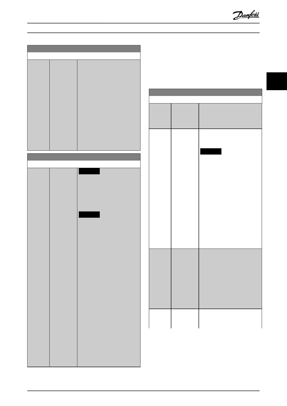
20-13 Minimum Reference/Feedb.
Range: Function:
0
ProcessCtrl
Unit*
[ -999999.999
- par. 20-14
ProcessCtrlUnit
]
Enter the desired minimum value
for the remote reference when
operating with
parameter 1-00 Conguration Mode
set for [3] Closed Loop operation.
Units are set in
parameter 20-12 Reference/Feedback
Unit.
Minimum feedback is -200% of
either the value set in
parameter 20-13 Minimum Reference/
Feedb. or in
parameter 20-14 Maximum
Reference/Feedb., which ever
numeric value is the highest.
20-14 Maximum Reference/Feedb.
Range: Function:
100
ProcessCtrl
Unit*
[ par. 20-13 -
999999.999
ProcessCtrlUnit
]
NOTICE
If operating with
parameter 1-00 Conguration
Mode set for [0] Open Loop,
use parameter 3-03 Maximum
Reference.
NOTICE
The dynamics of the PID
controller depends on the
value set in this parameter.
See also parameter 20-93 PID
Proportional Gain.
Parameter 20-13 Minimum
Reference/Feedb. and
parameter 20-14 Maximum
Reference/Feedb. also
determine the feedback range
when using feedback for
display readout with
parameter 1-00 Conguration
Mode set for [0] Open Loop.
Same condition as above.
Enter the maximum reference/
feedback for closed-loop operation.
The setting determines the highest
value obtainable by summing all
reference sources for closed-loop
operation. The setting determines
100% feedback in open and closed
loop (total feedback range: -200%
to +200%).
3.18.2 20-2* Feedback/Setpoint
This parameter group is used to determine how the PID
controller uses the 3 possible feedback signals to control
the output frequency of the frequency converter. This
group is also used to store the 3 internal setpoint
references.
20-20 Feedback Function
Option: Function:
This parameter determines how the
3 possible feedbacks are used to
control the output frequency of the
frequency converter.
[0] Sum Sets up the PID controller to use
the sum of feedback 1, feedback 2,
and feedback 3 as the feedback.
NOTICE
Set any unused feedbacks to [0]
No Function in
•
Parameter 20-00 Feedback
1 Source.
•
Parameter 20-03 Feedback
2 Source.
•
Parameter 20-06 Feedback
3 Source.
The sum of setpoint 1 and any
other references that are enabled
(see parameter group 3-1*
References) are used as the PID
controller’s setpoint reference.
[1] Dierence Sets up the PID controller to use
the dierence between feedback 1
and feedback 2 as the feedback.
Feedback 3 is not used with this
selection. Only setpoint 1 is used.
The sum of setpoint 1 and any
other references that are enabled
(see parameter group 3-1*
References) are used as the PID
controller’s setpoint reference.
[2] Average Sets up the PID controller to use
the average of feedback 1, feedback
2, and feedback 3 as the feedback.
Parameter Descriptions Programming Guide
M0010001 Danfoss A/S © 10/2019 All rights reserved. 179
3 3
 Loading...


