Depending on the system being controlled, the time
required to carry out PID auto-tuning could be several
minutes.
Before activating the PID auto-tuning, remove excessive
feedback sensor noise using the input lter (parameter
groups 5-5* Pulse Input, 6-** Analog In/Out and 26-** Analog
I/O Option MCB 109, terminal 53/54 lter time constant,
and pulse lter time constant #29/33).
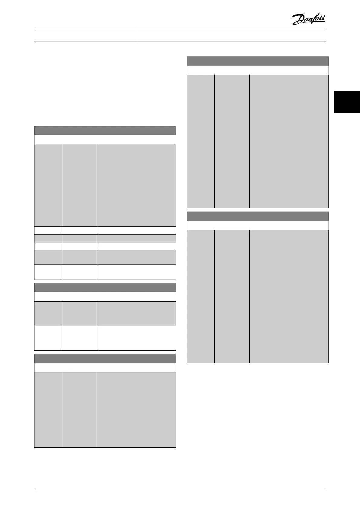
21-00 Closed Loop Type
Option: Function:
This parameter denes the
application response. The default
mode should be sucient for most
applications. If the relative
application speed is known, it can
be selected here. This decreases the
time needed for carrying out PID
auto-tuning. The setting has no
impact on the value of the tuned
parameters and is used only for the
PID auto-tuning sequence.
[0] * Auto
[1] Fast Pressure
[2] Slow Pressure
[3] Fast
Temperature
[4] Slow
Temperature
21-01 PID Performance
Option: Function:
[0] * Normal Normal setting of this parameter is
suitable for pressure control in fan
systems.
[1] Fast Fast setting would generally be
used in pumping systems, where a
faster control response is desirable.
21-02 PID Output Change
Range: Function:
0.10* [0.01 - 0.50 ] This parameter sets the magnitude
of step change during auto tuning.
The value is a percentage of full
operating range. That is, if the
maximum analog output voltage is
set to 10 V, 0.10 is 10% of 10 V,
which is 1 V. Set this parameter to
a value resulting in feedback
changes of 10–20% for best tuning
accuracy.
21-03 Minimum Feedback Level
Range: Function:
-999999* [ -999999.999
- par. 21-04 ]
Enter the minimum allowable
feedback level in user units as
dened in:
•
Parameter 21-10 Ext. 1 Ref./
Feedback Unit for EXT CL
1.
•
Parameter 21-30 Ext. 2 Ref./
Feedback Unit for EXT CL
2.
•
Parameter 21-50 Ext. 3 Ref./
Feedback Unit for EXT CL
3.
If the level drops below
parameter 21-03 Minimum Feedback
Level, PID auto-tuning is aborted,
and an error message appears in
the display.
21-04 Maximum Feedback Level
Range: Function:
999999* [ par. 21-03 -
999999.999 ]
Enter the maximum allowable
feedback level in user units as
dened in:
•
Parameter 21-10 Ext. 1 Ref./
Feedback Unit for EXT CL
1.
•
Parameter 21-30 Ext. 2 Ref./
Feedback Unit for EXT CL
2.
•
Parameter 21-50 Ext. 3 Ref./
Feedback Unit for EXT CL
3.
If the level rises above
parameter 21-04 Maximum Feedback
Level, PID auto tuning is aborted,
and an error message appears in
the display.
Parameter Descriptions Programming Guide
M0010001 Danfoss A/S © 10/2019 All rights reserved. 189
3 3
 Loading...


