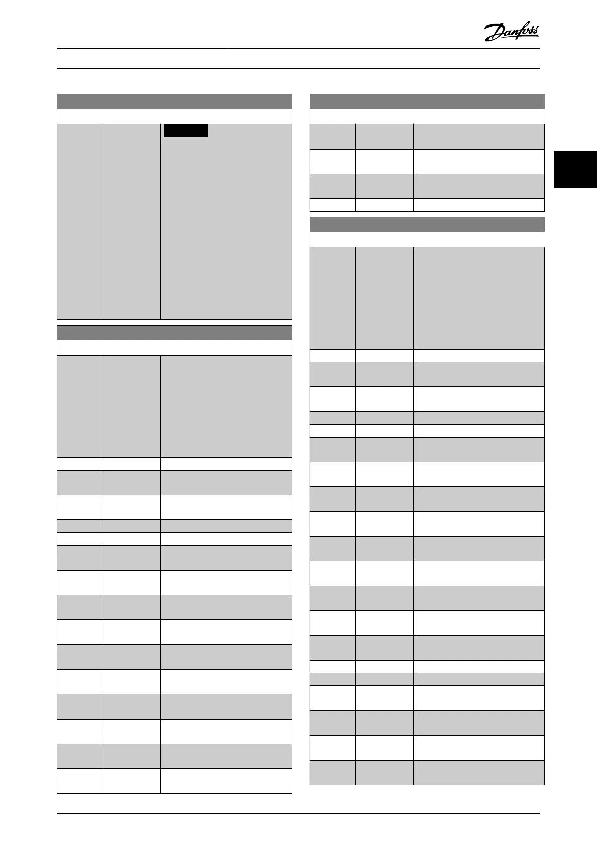
21-12 Ext. 1 Maximum Reference
Range: Function:
100
ExtPID1Uni
t*
[ par. 21-11 -
999999.999
ExtPID1Unit]
NOTICE
Set the value for
parameter 21-12 Ext. 1
Maximum Reference before
setting the values for the PID
controller in parameter group
20-9* PID Controller.
Select the maximum reference for
the closed-loop 1 controller.
The dynamics of the PID controller
depend on the value set in this
parameter. See also
parameter 21-21 Ext. 1 Proportional
Gain.
21-13 Ext. 1 Reference Source
Option: Function:
This parameter denes which input
on the frequency converter should
be treated as the source of the
reference signal for the closed-loop
1 controller. Analog input X30/11
and analog input X30/12 refer to
inputs on the VLT
®
General Purpose
I/O Card MCB 101.
[0] * No function
[1] Analog Input
53
[2] Analog Input
54
[7] Pulse input 29
[8] Pulse input 33
[20] Digital
pot.meter
[21] Analog input
X30/11
[22] Analog input
X30/12
[23] Analog Input
X42/1
[24] Analog Input
X42/3
[25] Analog Input
X42/5
[29] Analog Input
X48/2
[30] Ext. Closed
Loop 1
[31] Ext. Closed
Loop 2
[32] Ext. Closed
Loop 3
21-13 Ext. 1 Reference Source
Option: Function:
[37] Analog Input
X49/1
[38] Analog Input
X49/3
[39] Analog Input
X49/5
[133] Fieldbus REF 1
21-14 Ext. 1 Feedback Source
Option: Function:
This parameter denes which input
on the frequency converter should
be treated as the source of the
feedback signal for the closed-loop
1 controller. Analog input X30/11
and analog input X30/12 refer to
inputs on the VLT
®
General Purpose
I/O Card MCB 101.
[0] * No function
[1] Analog Input
53
[2] Analog Input
54
[3] Pulse input 29
[4] Pulse input 33
[7] Analog Input
X30/11
[8] Analog Input
X30/12
[9] Analog Input
X42/1
[10] Analog Input
X42/3
[11] Analog Input
X42/5
[15] Analog Input
X48/2
[16] Analog Input
X49/1
[17] Analog Input
X49/3
[18] Analog Input
X49/5
[19] Pressure 3
[20] Pressure 4
[99] Normal
Feedback
[100] Bus Feedback
1
[101] Bus Feedback
2
[102] Bus feedback
3
Parameter Descriptions Programming Guide
M0010001 Danfoss A/S © 10/2019 All rights reserved. 191
3 3
 Loading...


