1-93 Thermistor Source
Option: Function:
or parameter 3-17 Reference 3
Source).
When using VLT
®
PTC Thermistor
Card MCB 112, always select [0]
None.
[0] * None
[1] Analog Input
53
[2] Analog Input
54
[3] Digital input
18
[4] Digital input
19
[5] Digital input
32
[6] Digital input
33
1-94 ATEX ETR cur.lim. speed reduction
Range: Function:
0 %* [0 - 100 %] Only visible if parameter 1-90 Motor
Thermal Protection is set to [20]
ATEX ETR.
Congure the reaction for operating in Ex-e current limit.
0%: The frequency converter does not change anything
besides issuing warning 163, ATEX ETR cur.lim.warning.
>0%: The frequency converter issues warning 163, ATEX ETR
cur.lim.warning and reduces motor speed following ramp 2
(parameter group 3-5* Ramp 2).
Example:
Actual reference = 50 RPM
Parameter 1-94 ATEX ETR cur.lim. speed reduction = 20%
Resulting reference = 40 RPM
1-95 Thermistor Sensor Type
Option: Function:
Select the type of the thermistor
sensor.
[0] * KTY Sensor 1
1 kΩ at 100 °C (212 °F).
[1] KTY Sensor 2
1 kΩ at 25 °C (77 °F).
[2] KTY Sensor 3
2 kΩ at 25 °C (77 °F).
[3] Pt1000
1-96 Thermistor Sensor Source
Option: Function:
Select analog input terminal 54 as a
thermistor sensor input. Terminal 54
cannot be selected as thermistor
source if otherwise used as
1-96 Thermistor Sensor Source
Option: Function:
reference (see
parameter 3-15 Reference Resource 1
to parameter 3-17 Reference Resource
3).
NOTICE
Connection of thermistor
sensor between terminals 54
and 55 (GND).
[0] * None
[2] Analog Input
54
1-97 Thermistor Threshold level
Range: Function:
80 °C* [ -40 -
220 °C]
Select the thermistor sensor
threshold level for motor thermal
protection.
1-98 ATEX ETR interpol. points freq.
Range: Function:
Size
related*
[ 0 - 1000.0
Hz]
NOTICE
Valid for only.
Only visible if parameter 1-90 Motor
Thermal Protection is set to [20].
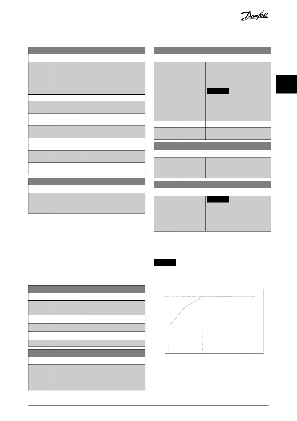
Enter the 4 frequency points [Hz] from the motor
nameplate into this array. Table 3.10 shows the example of
frequency/current points.
NOTICE
All frequency/current limit points from the motor
nameplate or motor datasheet must be programmed.
8 0 %
4 0 %
5 Hz 15 Hz 25 Hz 50 Hz
130BB909.10
Illustration 3.16 Example of ATEX ETR Thermal Limitation
Curve
x-axis: f
m
[Hz]
Parameter Descriptions Programming Guide
M0010001 Danfoss A/S © 10/2019 All rights reserved. 69
3 3
 Loading...


