555039 42 53 54
R
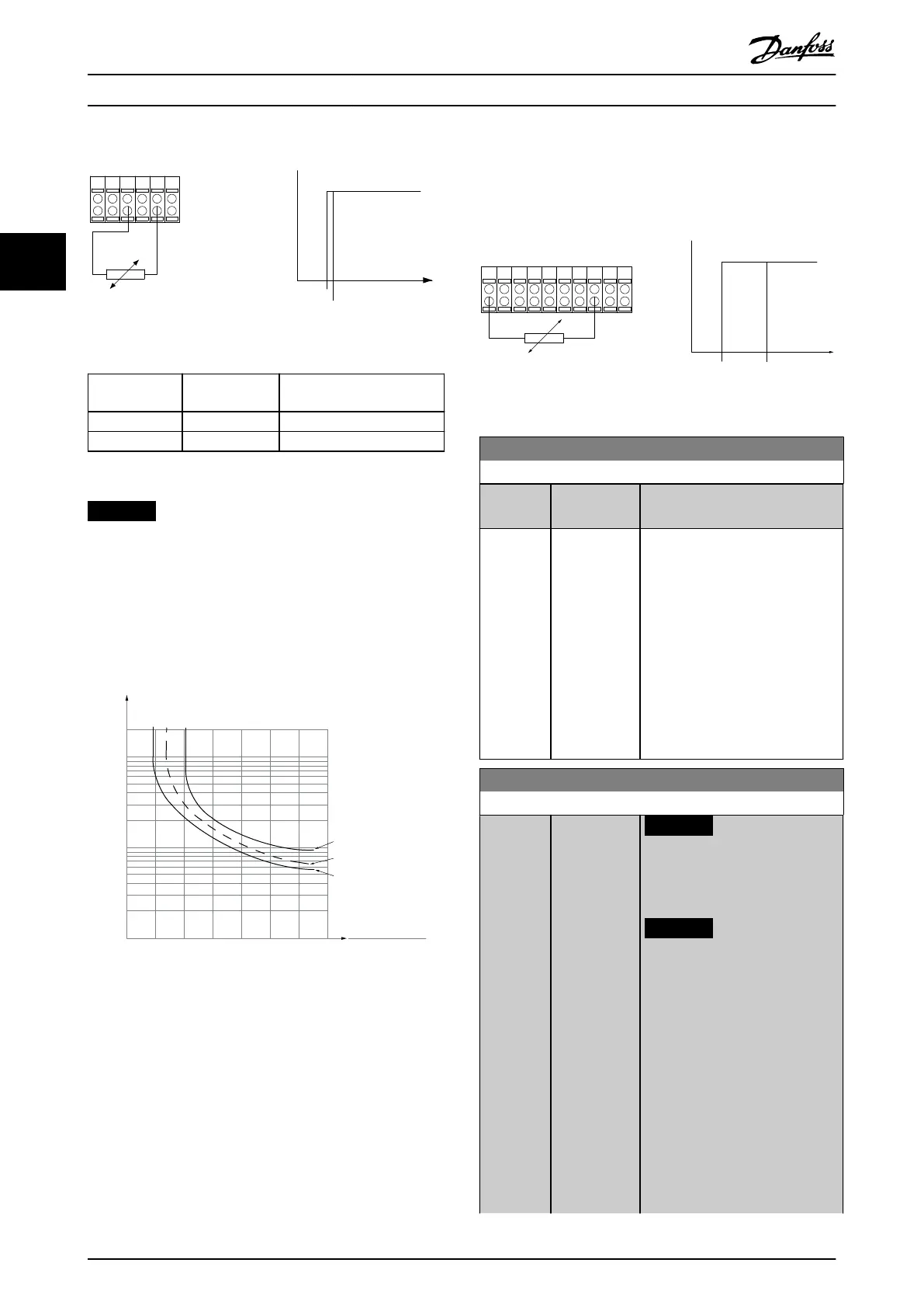
<3.0 k Ω
>3.0 k Ω
+10V
130BA153.11
PTC / Thermistor
OFF
ON
Illustration 3.13 PTC Thermistor Connection - Analog Input
Input
digital/analog
Supply voltage
[V]
Threshold
cutout values.
Digital 10
<800 Ω⇒2.7 kΩ
Analog 10
<3.0 kΩ⇒3.0 kΩ
Table 3.9 Threshold Cutout Values
NOTICE
Check that the selected supply voltage follows the
specication of the used thermistor element.
3.3.13.2 ETR
The calculations estimate the need for a lower load at
lower speed due to less cooling from the fan incorporated
in the motor.
1.21.0 1.4
30
10
20
100
60
40
50
1.81.6 2.0
2000
500
200
400
300
1000
600
t [s]
175ZA052.12
f
OUT
= 2 x f
M,N
f
OUT
= 0.2 x f
M,N
f
OUT
= 1 x f
M,N
(par. 1-23)
I
MN
(par. 1-24)
I
M
Illustration 3.14 ETR Prole
3.3.13.3 Klixon
The Klixon type thermal circuit breaker uses a KLIXON
®
metal dish. At a predetermined overload, the heat caused
by the current through the disc causes a trip.
Example using a digital input and 24 V as supply
The frequency converter trips when the motor temperature
is too high.
Parameter set-up:
•
Set parameter 1-90 Motor Thermal Protection to [2]
Thermistor Trip.
•
Set parameter 1-93 Thermistor Source to [6] Digital
Input.
PTC / Thermistor
OFF
ON
+24V
12 13 18 3732
A
2719 29 33
B
20
GND
R<6.6 k Ω >10.8 k Ω
130BA151.11
Illustration 3.15 Thermistor Connection
1-91 Motor External Fan
Option: Function:
[0] * No No external fan is required, that is,
the motor is derated at low speed.
[1] Yes Applies an external motor fan
(external ventilation), so no
derating of the motor is required at
low speed. The upper curve in
Illustration 3.14 (f
out
= 1 x f
M,N
) is
followed if the motor current is
lower than nominal motor current
(see parameter 1-24 Motor Current).
If the motor current exceeds
nominal current, the operation time
still decreases as if no fan was
installed.
1-93 Thermistor Source
Option: Function:
NOTICE
This parameter cannot be
adjusted while the motor is
running.
NOTICE
Set digital input to [0] PNP -
Active at 24 V in
parameter 5-00 Digital I/O
Mode.
Select the input to which the
thermistor (PTC sensor) should be
connected. An analog input option
[1] Analog Input 53 or [2] Analog
Input 54 cannot be selected if the
analog input is already in use as a
reference source (selected in
parameter 3-15 Reference 1 Source,
parameter 3-16 Reference 2 Source,
Parameter Descriptions
VLT
®
HVAC Drive FC 102
68 Danfoss A/S © 10/2019 All rights reserved. M0010001
33
 Loading...


