•
•
•
•
•
•
•
•
•
•
-
-
-
-
-
-
4.3 Grounding
W A R N I N G
ELECTRICAL SHOCK HAZARD - LEAKAGE CURRENT HAZARD >3.5 MA
Leakage currents exceed 3.5 mA. Failure to connect the drive properly to protective earth (PE) can result in death or serious in-
jury.
Ensure reinforced protective earthing conductor according to IEC 60364-5-54 cl. 543.7 or according to local safety regula-
tions for high touch current equipment. The reinforced protective earthing of the drive can be done with:
a PE conductor with a cross-section of at least 10 mm
2
(8 AWG) Cu or 16 mm
2
(6 AWG) Al.
an extra PE conductor of the same cross-sectional area as the original PE conductor as specified by IEC 60364-5-54 with a
minimum cross-sectional area of 2.5 mm
2
(14 AWG) (mechanical protected) or 4 mm
2
(12 AWG) (not mechanical protected).
a PE conductor completely enclosed with an enclosure or otherwise protected throughout its length against mechanical
damage.
a PE conductor part of a multi-conductor power cable with a minimum PE conductor cross-section of 2.5 mm
2
(14 AWG)
(permanently connected or pluggable by an industrial connector. The multi-conductor power cable shall be installed with an
appropriate strain relief).
NOTE: In IEC/EN 60364-5-54 cl. 543.7 and some application standards (for example IEC/EN 60204-1), the limit for requiring
reinforced protective earthing conductor is 10 mA leakage current.
For electrical safety
Ground the drive in accordance with applicable standards and directives.
Use a dedicated ground wire for input power, motor power, and control wiring.
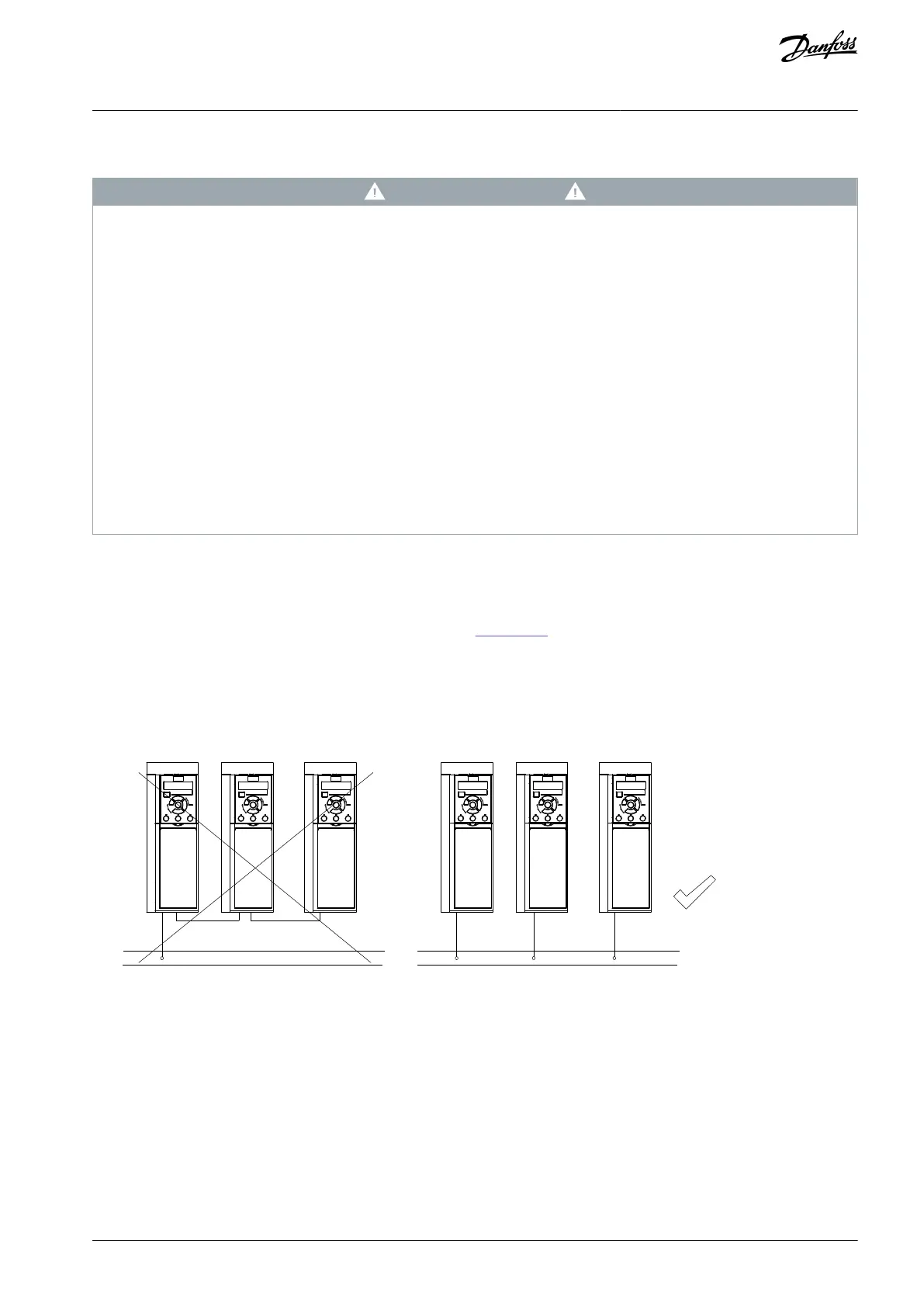
Do not ground 1 drive to another in a daisy chain fashion (see
Illustration 7).
Keep the ground wire connections as short as possible.
Follow motor manufacturer wiring requirements.
Minimum cable cross-section for the ground wires: 10 mm
2
(7 AWG).
Separately terminate individual ground wires, both complying with the dimension requirements.
e30bc500.12
FC 1
FC 1
FC 2
FC 2
FC 3
FC 3
PE
PE
A
B
Illustration 7: Grounding Principle
For EMC-compliant installation
Establish electrical contact between the cable shield and the drive enclosure by using metal cable glands or by using the clamps
provided on the equipment.
Use high-strand wire to reduce burst transient.
Do not use pigtails.
AQ267037536117en-000101 / 130R0083 | 21Danfoss A/S © 2023.09
Electrical Installation
VLT HVAC Drive FC 102
Operating Guide
 Loading...


