-
-
-
-
•
-
-
-
-
4 programmable digital input terminals.
2 additional digital terminals programmable as either input or output.
A 24 V DC terminal supply voltage.
A common for optional customer-supplied 24 V DC voltage.
Analog input/output connector provides:
2 analog inputs.
1 analog output.
10 V DC supply voltage.
Commons for the inputs and output.
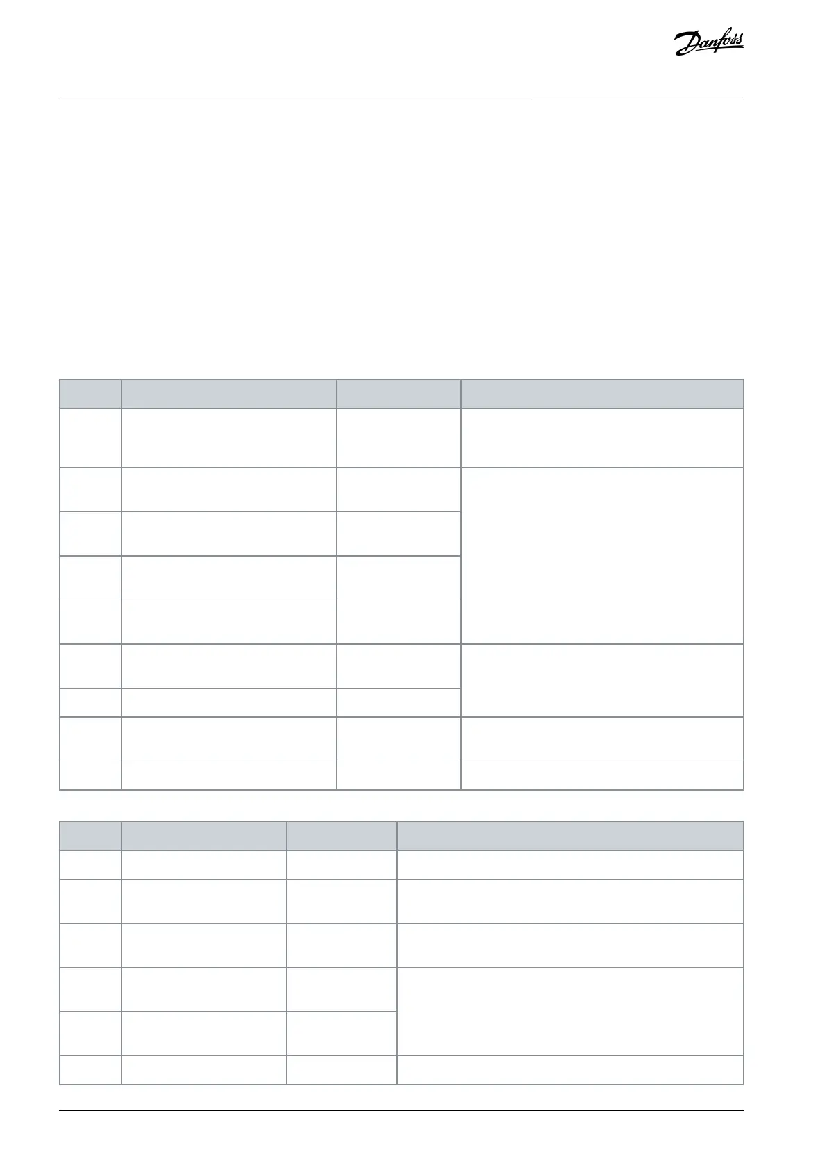
4.8.3 Terminal Descriptions
Table 6: Digital Inputs/Outputs
+24 V DC supply voltage for digital inputs and ex-
ternal transducers. Maximum output current
200 mA for all 24 V loads.
Parameter 5-10 Terminal 18 Digital In-
puts
Parameter 5-11 Terminal 19 Digital In-
puts
Parameter 5-14 Terminal 32 Digital In-
put
Parameter 5-15 Terminal 33 Digital In-
put
Parameter 5-12 Terminal 27 Digital In-
put
For digital input or output. Default setting is input.
Parameter Terminal 29 Digital Input
Common for digital inputs and 0 V potential for
24 V supply.
Safe input (optional). Used for STO.
Table 7: Analog Inputs/Outputs
Common for analog output.
Parameter 6-50 Terminal 42
Output
Programmable analog output. 0–20 mA or 4–20 mA at a maxi-
mum of 500 Ω.
10 V DC analog supply voltage potentiometer or thermistor.
15 mA maximum.
Parameter group 6-1* Analog
Input 1
Analog input. For voltage or current. Switches A53 and A54 se-
lect mA or V.
Parameter group 6-1* Analog
Input 2
AQ267037536117en-000101 / 130R008332 | Danfoss A/S © 2023.09
Electrical Installation
VLT HVAC Drive FC 102
Operating Guide
 Loading...


