•
•
•
6 Basic I/O Configuration
6.1 Application Examples
The examples in this section are intended as a quick reference for common applications.
Parameter settings are the regional default values unless otherwise indicated (selected in parameter 0-03 Regional Settings).
Parameters associated with the terminals and their settings are shown next to the drawings.
Required switch settings for analog terminals A53 or A54 are also shown.
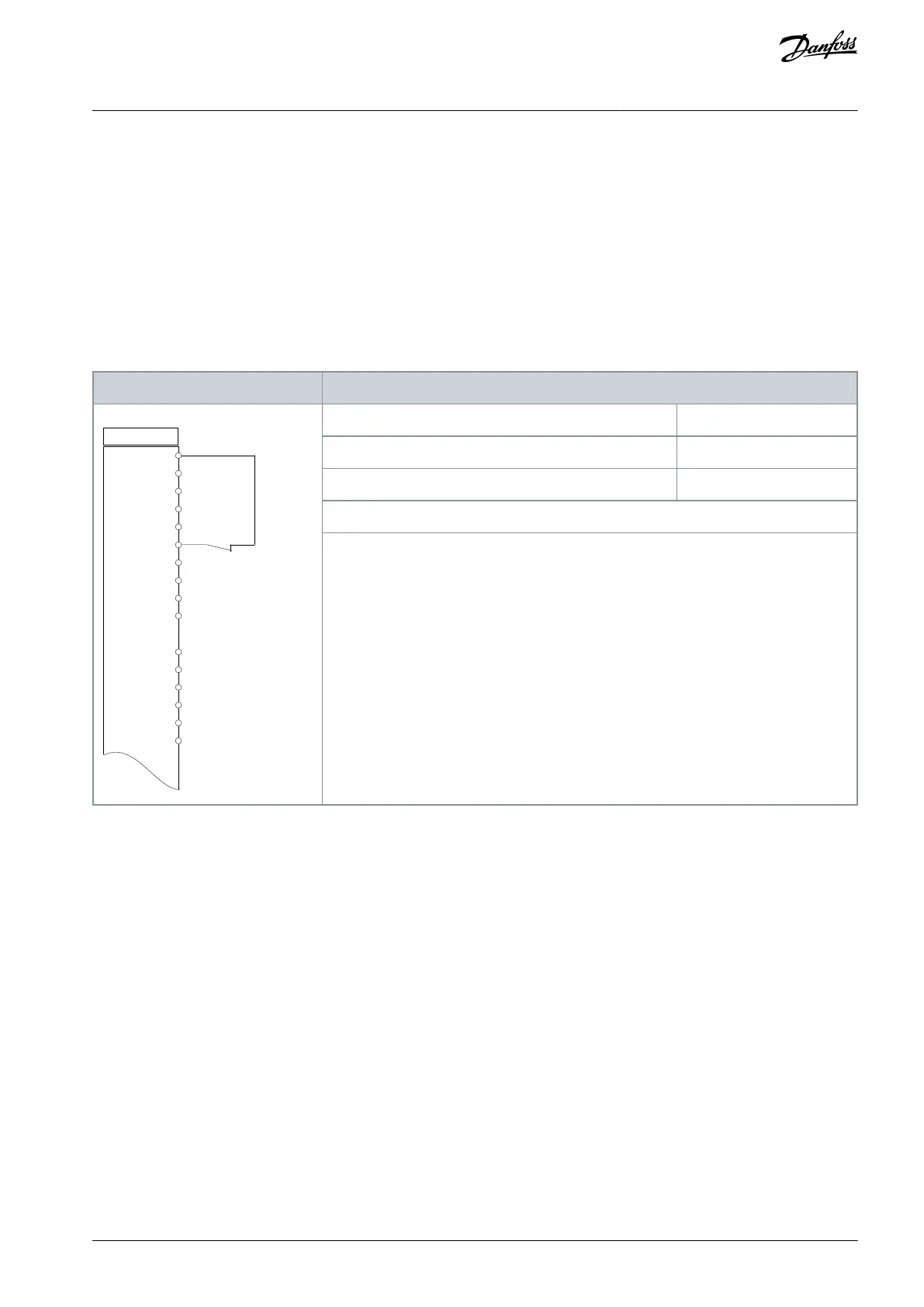
6.1.1 Wiring Configuration for Automatic Motor Adaptation (AMA)
Table 19: Wiring Configuration for AMA with T27 Connected
+24 V
+24 V
D IN
D IN
D IN
COM
D IN
D IN
D IN
D IN
+10 V
A IN
A IN
COM
A OUT
COM
12
13
18
19
20
27
29
32
33
37
50
53
54
55
42
39
e30bb929.11
Parameter 1-29 Automatic Motor Adaptation (AMA)
Parameter 5-12 Terminal 27 Digital Input
Notes/comments:
Set parameter group 1-2* Motor Data according to motor nameplate.
AQ267037536117en-000101 / 130R0083 | 47Danfoss A/S © 2023.09
Basic I/O Configuration
VLT HVAC Drive FC 102
Operating Guide

 Loading...


