6.1.11 Wiring Configuration for a Relay Setup with Smart Logic Control
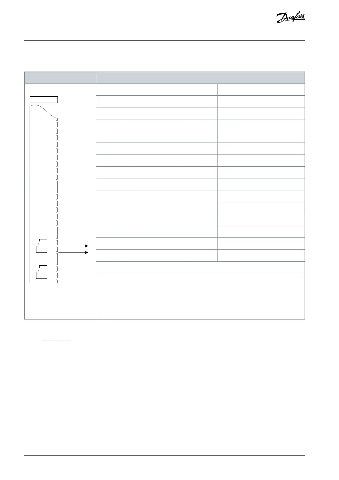
Table 38: Wiring Configuration for a Relay Setup with Smart Logic Control
+24 V
+24 V
D IN
D IN
D IN
COM
D IN
D IN
D IN
D IN
+10 V
A IN
A IN
COM
A OUT
COM
R 1 R 2
12
13
18
19
20
27
29
32
33
37
50
53
54
55
42
39
01
02
03
04
05
06
130BB839.10
Drive
Parameter 4-30 Motor Feedback Loss Function
Parameter 4-31 Motor Feedback Speed Error
Parameter 4-32 Motor Feedback Loss Timeout
Parameter 7-00 Speed PID Feedback Source
Parameter 17-11 Resolution (PPR)
Parameter 13-00 SL Controller Mode
Parameter 13-01 Start Event
Parameter 13-02 Stop Event
Parameter 13-10 Comparator Operand
Parameter 13-11 Comparator Operator
Parameter 13-12 Comparator Value
Parameter 13-51 SL Controller Event
Parameter 13-52 SL Controller Action
[32] Set digital out A low
Parameter 5-40 Function Relay
Notes/comments:
If the limit in the feedback monitor is exceeded, warning 90, Feedback Mon. is issued. The SLC
monitors warning 90, Feedback Mon. and if the warning becomes true, relay 1 is triggered. Ex-
ternal equipment may require service. If the feedback error goes below the limit again within
5 s, the drive continues and the warning disappears. Reset relay 1 by pressing [Reset] on the
LCP.
6.1.12 Wiring Configuration for a Cascade Controller
Refer to Illustration 27 for an example with the built-in basic cascade controller with 1 variable-speed pump (lead) and 2 fixed-speed
pumps, a 4–20 mA transmitter, and system safety interlock.
AQ267037536117en-000101 / 130R008360 | Danfoss A/S © 2023.09
Basic I/O Configuration
VLT HVAC Drive FC 102
Operating Guide

 Loading...


