2.
3.
4.
5.
1.
2.
3.
4.
5.
6.
7.
8.
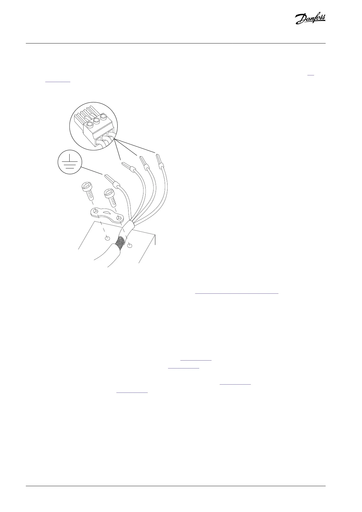
Position the stripped wire under the cable clamp to establish mechanical fixation and electrical contact between cable
shield and ground.
Connect the ground wire to the nearest grounding terminal in accordance with grounding instructions provided in 4.3
Grounding.
Connect the 3-phase motor wiring to terminals 96 (U), 97 (V), and 98 (W).
Illustration 12: Motor Connection
Tighten terminals in accordance with the information provided in 8.11 Connection Tightening Torques.
4.6.2 Grounding with Category C1 Filter
Check the filter category in the typecode on the nameplate.
Procedure
Strip a section of the outer cable insulation.
Position the stripped wire under the cable clamp to establish mechanical fixation and electrical contact between cable
shield and ground.
Run the 3-phase motor wiring through the rubber part, see Illustration 13.
Run the 3-phase motor wiring through the ferrite, see Illustration 13.
Connect ground wire to the nearest grounding terminal in accordance with grounding instructions.
Connect the 3-phase motor wiring to terminals 96 (U), 97 (V), and 98 (W), see Illustration 13.
Position the ferrite as shown in Illustration 13.
Squeeze the plastic clamps together. Use the teeth lock to fasten the ferrite to the wires.
AQ267037536117en-000101 / 130R008326 | Danfoss A/S © 2023.09
Electrical Installation
VLT HVAC Drive FC 102
Operating Guide
 Loading...


