N O T I C E
POTENTIAL EQUALIZATION
Risk of burst transient when the ground potential between the drive and the control system is different. Install equalizing cables
between the system components. Recommended cable cross-section: 16 mm
2
(6 AWG).
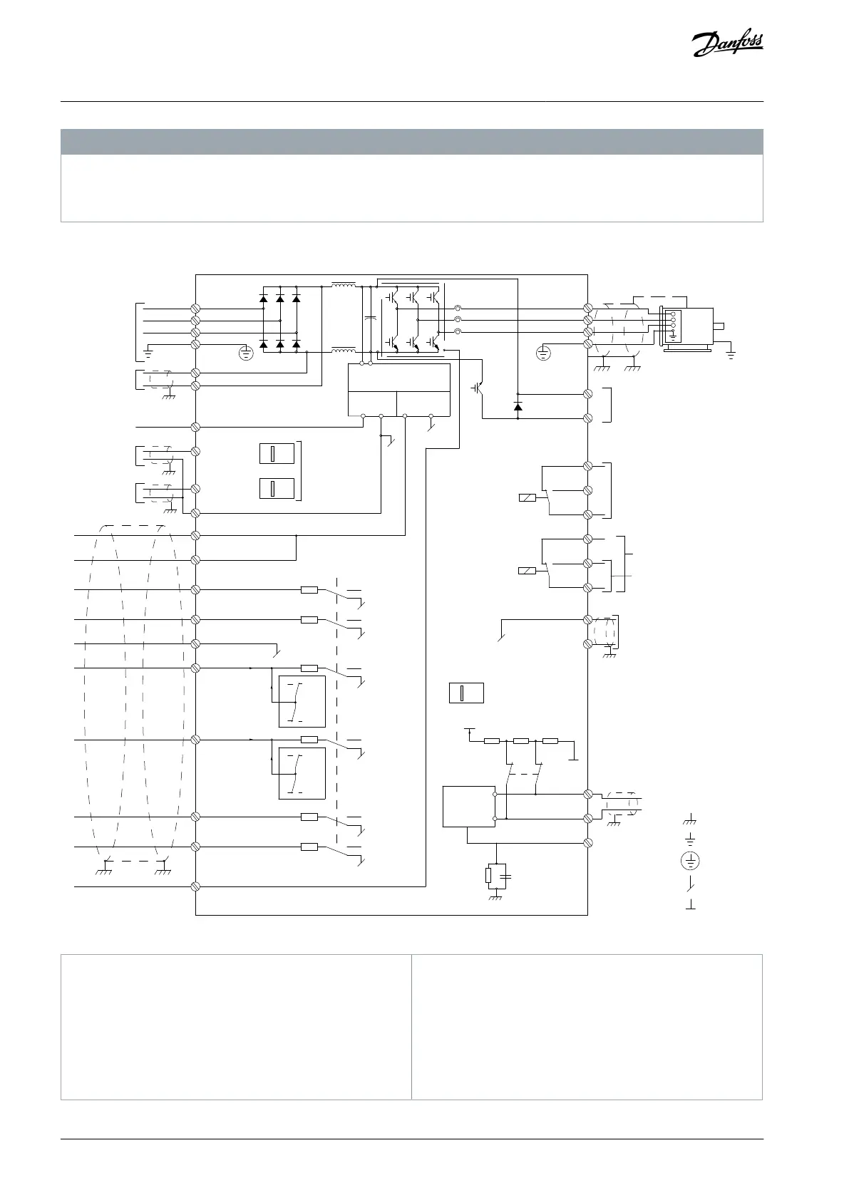
4.4 Wiring Schematic
relay1
relay2
ON=Terminated
OFF=Open
88 (-)
89 (+)
50 (+10 V OUT)
12 (+24 V OUT)
13 (+24 V OUT)
37 (D IN)
18 (D IN)
20 (COM D IN)
(COM A OUT) 39
(A OUT) 42
(P RS-485) 68
(N RS-485) 69
(COM RS-485) 61
0 V
5V
S801
0/4-20 mA
RS-485
RS-485
03
+10 V DC
02
01
05
04
06
24 V (NPN)
0 V (PNP)
0 V (PNP)
24 V (NPN)
19 (D IN)
24 V (NPN)
0 V (PNP)
27
24 V
0 V
(D IN/OUT)
0 V (PNP)
24 V (NPN)
(D IN/OUT)
0 V
24 V
29
24 V (NPN)
0 V (PNP)
0 V (PNP)
24 V (NPN)
33 (D IN)
32 (D IN)
1
A54
ON=0/4-20 mA
OFF=0/-10 V DC -
+10 V DC
95
P 5-00
21
ON
S801
(R+) 82
240 V AC, 2 A
400 V AC, 2 A
: Ground 1
: Ground 2
: Ground
Illustration 8: Basic Wiring Schematic
Terminal 37 (optional) is used for Safe Torque Off.
For Safe Torque Off installation instructions, refer to
the Safe Torque Off Operating Guide for Danfoss
VLT
®
Frequency Converters.
Do not connect cable shield.
For 1-phase power input, wire to L1 and L2.
AQ267037536117en-000101 / 130R008322 | Danfoss A/S © 2023.09
Electrical Installation
VLT HVAC Drive FC 102
Operating Guide
 Loading...


