1.
2.
3.
Table 8: Serial Communication
Integrated RC-filter for cable shield. ONLY for connecting the shield if
EMC problems occur.
Parameter group 8-3* FC Port
Settings
RS485 interface. A control card switch is provided for termination re-
sistance.
Parameter group 8-3* FC Port
Settings
Table 9: Relays
Parameter 5-40 Function Relay [0]
Form C relay output. For AC or DC voltage and resistive or in-
ductive loads.
Parameter 5-40 Function Relay [1]
Table 10: Additional Terminals
The location of the outputs depend on the drive configuration.
Terminals on built-in optional equipment
See the manual provided with the equipment option.
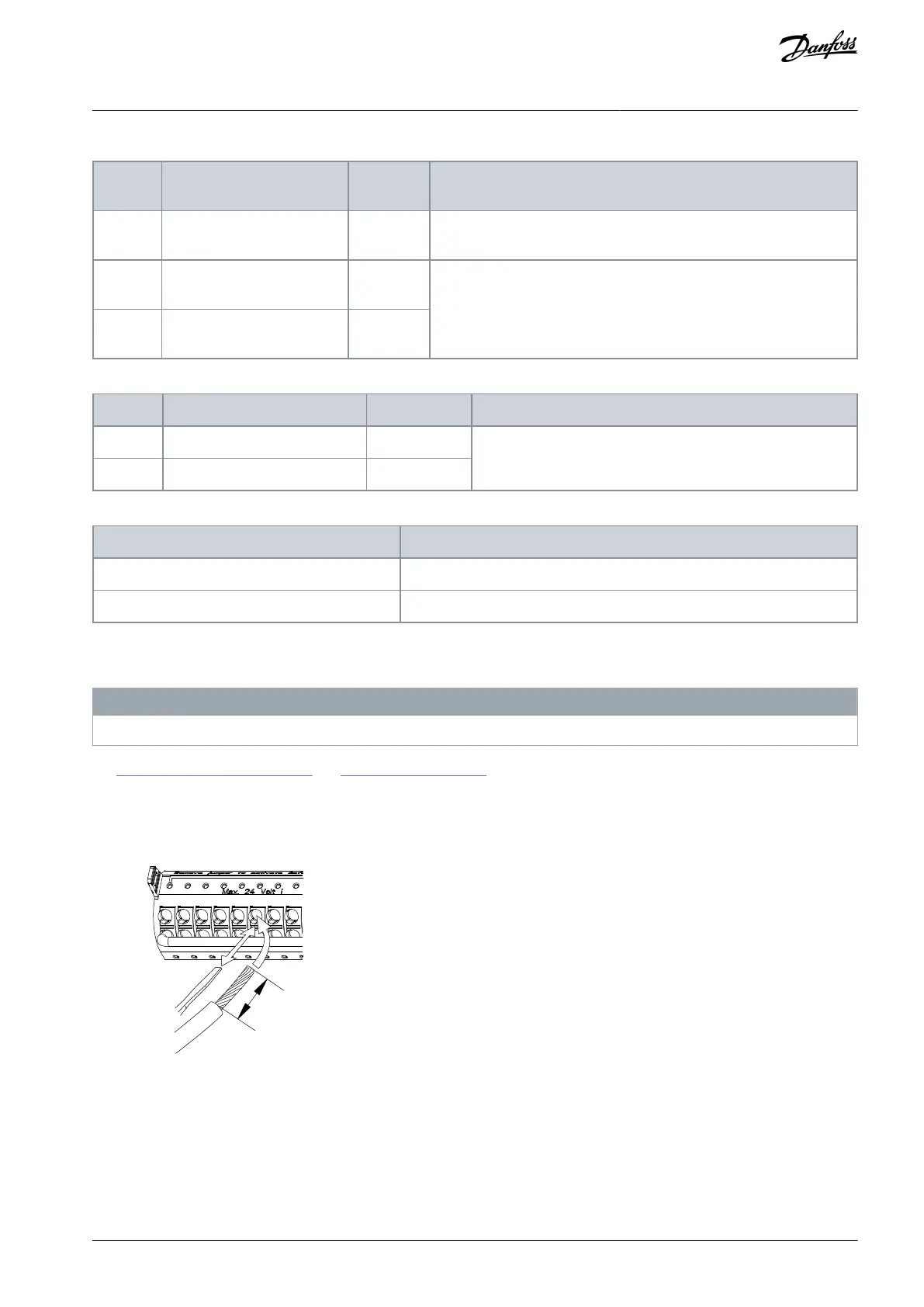
4.8.4 Wiring to Control Terminals
Control terminal connectors can be unplugged from the drive for ease of installation as shown in the next drawing.
N O T I C E
Keep control wires as short as possible and separate from high power cables to minimize interference.
See 8.8.3 Control Cable Cross-sections and 6.1 Application Examples for typical control wiring connections.
Procedure
Open the contact by inserting a flathead screwdriver (maximum head width 4 mm/no. 1) into the slot above the contact
and push the screwdriver slightly upwards.
Insert the bared control wire into the contact.
Remove the screwdriver to fasten the control wire into the contact.
AQ267037536117en-000101 / 130R0083 | 33Danfoss A/S © 2023.09
Electrical Installation
VLT HVAC Drive FC 102
Operating Guide
 Loading...


