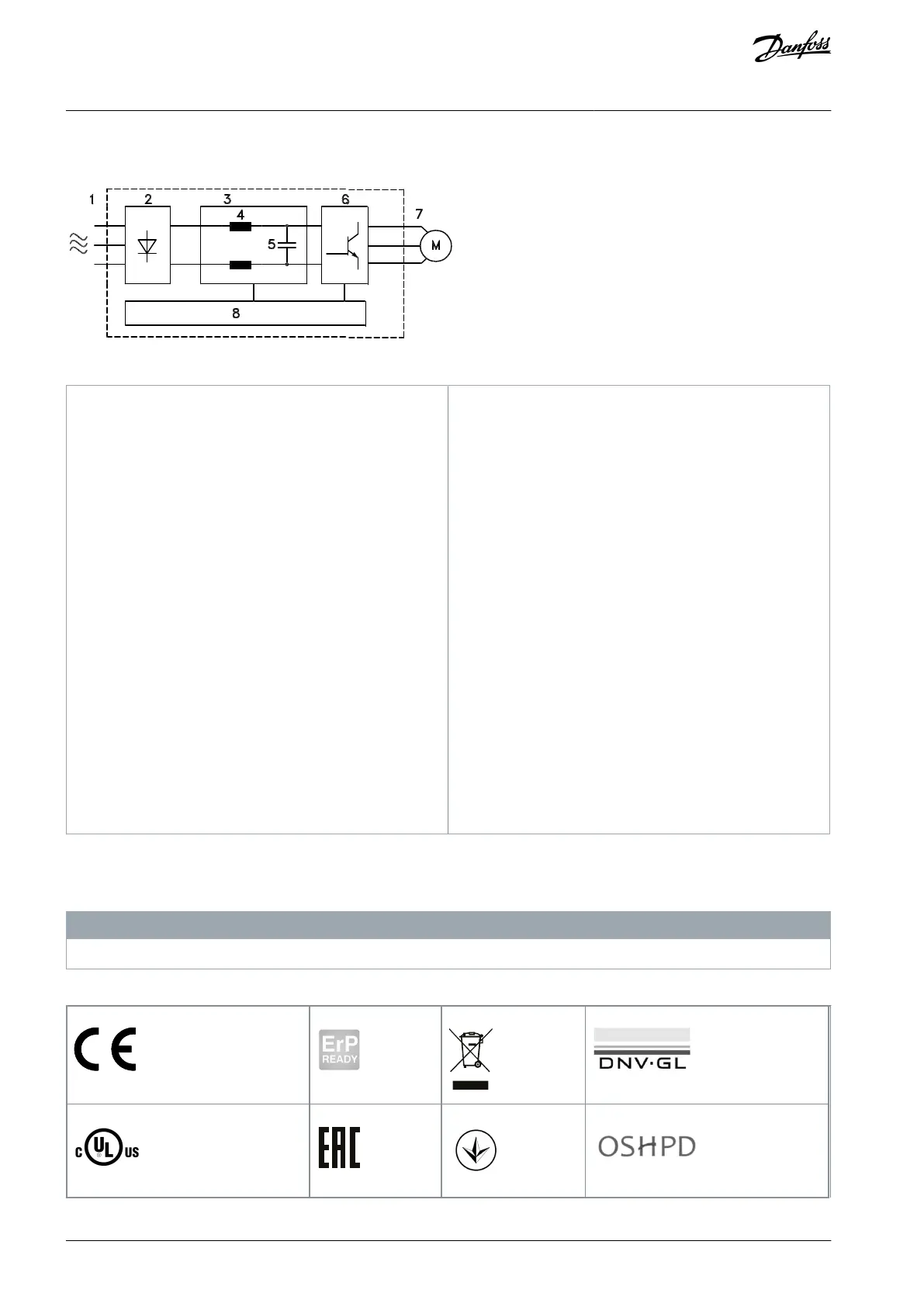
1.3.3 Block Diagram of the Drive
Illustration 3: Block Diagram
Mains input
3-phase AC mains power supply to the drive.
Rectifier
The rectifier bridge converts the AC input to DC
current to supply inverter power.
DC bus
Intermediate DC-bus circuit handles the DC cur-
rent.
DC reactors
Filter the intermediate DC circuit voltage.
Prove line transient protection.
Reduce RMS current.
Raise the power factor reflected back to the line.
Reduce harmonics on the AC input.
Capacitor bank
Stores the DC power.
Proves ride-through protection for short power
losses.
Inverter
Converts the DC into a controlled PWM AC
waveform for a controlled variable output to the
motor.
Output to motor
Regulated 3-phase output power to the motor.
Control circuitry
Input power, internal processing, output, and
motor current are monitored to provide efficient
operation and control.
User interface and external commands are
monitored and performed.
Status output and control can be provided.
1.4 Type Approvals and Certifications
The following list is a selection of possible type approvals and certifications for Danfoss drives:
N O T I C E
Drives of enclosure size T7 (525–690 V) are not UL listed.
Table 2: Type Approvals and Certifications
AQ267037536117en-000101 / 130R008310 | Danfoss A/S © 2023.09
Introduction
VLT HVAC Drive FC 102
Operating Guide

 Loading...


