EasyManuals Logo

Danfoss vlt FC 102 Operating Guide

Danfoss vlt FC 102
120 pages
To Next Page IconTo Next Page
To Previous Page IconTo Previous Page
Page #9 background imageLoading...
Page #9 background image
1
2
3
4
5
6
7
8
9
10
11
12
13
16
17
18
19
14
15
FAN MOUNTING
QDF-30
DC-
DC+
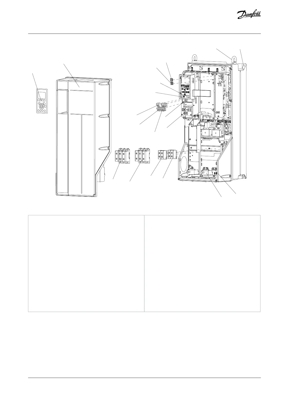
Remove jumper to activate Safe Stop
Max. 24 Volt !
12
13
18
19
27
29
32
33
20
37
06
05 04
03 02 01
e30bb493.12
Illustration 2: Exploded View Enclosure Types B and C, IP55 and IP66
1
Local control panel (LCP)
2
Cover
3
RS485 serial bus connector
4
Digital I/O and 24 V power supply
5
Analog I/O connector
6
Cable shield connector
7
USB connector
8
Serial bus terminal switch
9
Analog switches (A53), (A54)
10
Relay 1 (01, 02, 03)
11
Relay 2 (04, 05, 06)
12
Lifting ring
13
Mounting slot
14
Grounding clamp (PE)
15
Cable shield connector
16
Brake terminal (-81, +82)
17
Load sharing terminal (DC bus) (-88, +89)
18
Motor output terminals 96 (U), 97 (V), 98 (W)
19
Mains input terminals 91 (L1), 92 (L2), (L3)
AQ267037536117en-000101 / 130R0083 | 9Danfoss A/S © 2023.09
Introduction
VLT HVAC Drive FC 102
Operating Guide

Table of Contents

Other manuals for Danfoss vlt FC 102

Questions and Answers:

Question and Answer IconNeed help?

Do you have a question about the Danfoss vlt FC 102 and is the answer not in the manual?

Danfoss vlt FC 102 Specifications

General IconGeneral
CategoryDC Drives
ModelDanfoss VLT FC 102
Output voltage range0 to rated motor voltage
Power range0.37 kW to 200 kW
Communication interfacesRS-485
Protection featuresOvervoltage, undervoltage, overcurrent, short circuit, earth fault, overtemperature, motor thermal protection
Cooling methodAir-cooled
Enclosure ratingIP20, IP21, IP55 (depending on model)
ApprovalsCE, UL, cUL

Related product manuals