•
•
•
•
•
4.8 Control Terminals
4.8.1 Control Wiring
Isolate control wiring from high power components in the drive.
When the drive is connected to a thermistor, ensure that the thermistor control wiring is shielded and reinforced/double insula-
ted. A 24 V DC supply voltage is recommended.
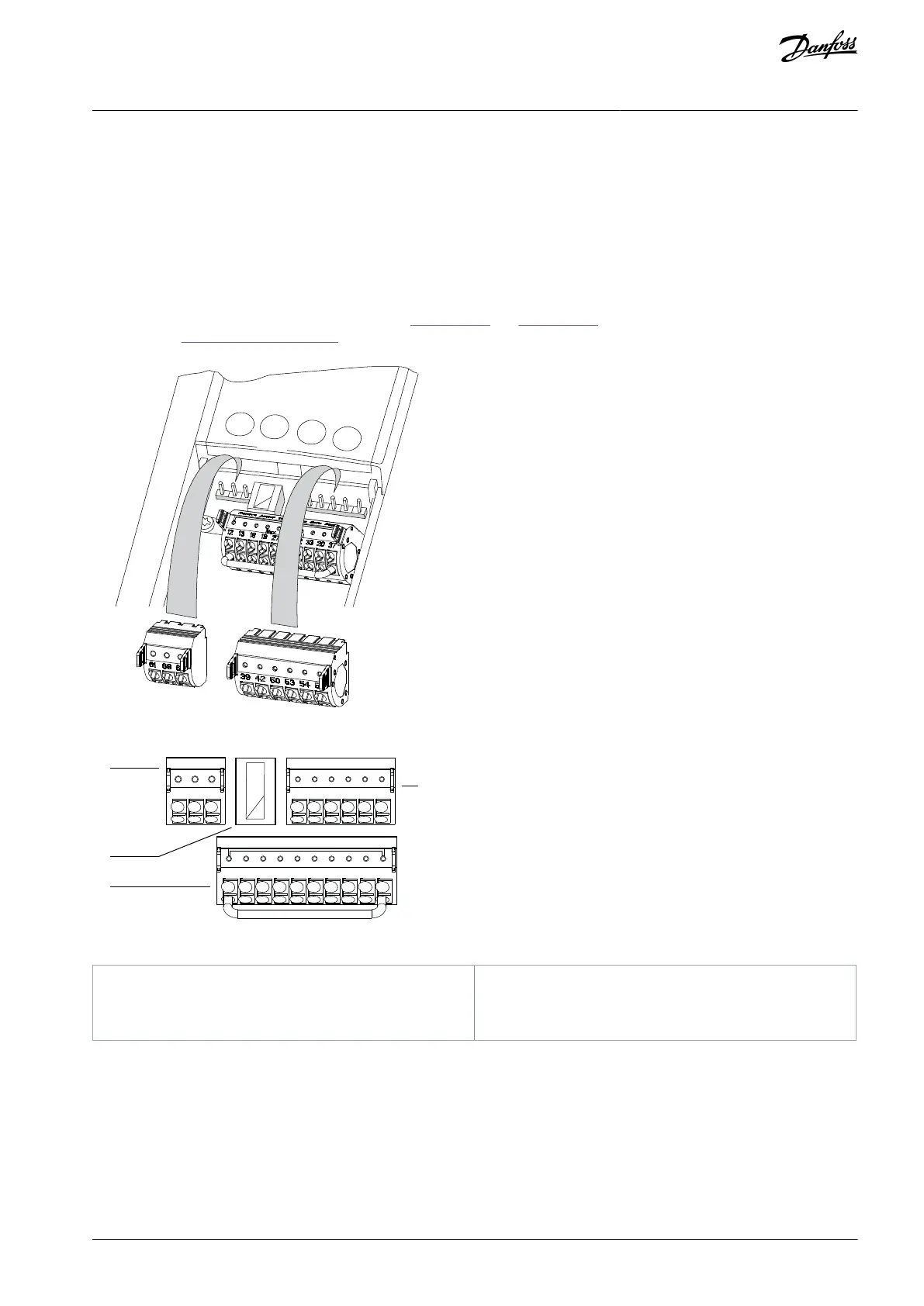
4.8.2 Control Terminal Types
Find the location of the removable drive connectors in Illustration 21 and Illustration 22. Terminal functions and default settings are
summarized in 4.8.3 Terminal Descriptions.
Illustration 21: Control Terminal Locations
12 13 18 19 27 29 32 33 20 37
39
696861
42 50 53 54 55
e30bf145.11
1
2
4
3
Illustration 22: Terminal Numbers on the Connectors
Serial communication connector
Digital input/output connector
Analog input/output connector
Serial communication connector provides 2 terminals (+)68 and (-)69 for an RS485 serial communication.
USB port available for use with the MCT 10 Set-up Software.
Digital input/output connector provides:
AQ267037536117en-000101 / 130R0083 | 31Danfoss A/S © 2023.09
Electrical Installation
VLT HVAC Drive FC 102
Operating Guide

 Loading...


